Which BOM are you referring to and where is it posted?While looking up the McMaster Carr parts on the BOM I noticed a couple discrepancies in part numbers.
M3 x 10mm screws are listed as 91292A112 but are actually 8mm, the 10mm version is 91292A113
6-32 x 5/8" screws are listed as 92196A144 but are actually 1/4", the 5/8" version is 92196A150
For R3-7 the schematic and parts list mention 2W resistors, but the part numbers listed are 3W which are also what's in the kit. Is 2W ok in these spots or should they all be 3W as the part numbers/kit suggest?
What is currently being shipped in the completion kit are the 10mm screws to provide adequate number of threads gripping the sinks. The 5/8" screws are for the boards.
2W resistors are fine. These were originally spec'd by Nelson, but I was able to find 3W Vishay for the same price so it's a little added value. 🙂

Which BOM are you referring to and where is it posted?
The first post if this thread, both versions on page 6.
F5M DIY AMPLIFIER.pdf
F5M DIY AMPLIFIER R1.pdf
The completion kit for the F5m that just shipped to the store is version R2. It will now contain only those parts necessary to complete the amplifier portion of this project. The power supply PSU-A-V1R1 will be sold as a separate kit. It incorporates improvements that Nelson designed back in April.
Updated BOMs will be listed on their respective pages on the store website.

Updated BOMs will be listed on their respective pages on the store website.
1st f5m power up this am. As I ramped up the variac the power boards emitted the dreaded smoke. Thought it was the right channel only, tested again w/left channel only same thing. Nothing charred or even warm. Loosened and checked all 3 boards for slag or foreign parts, inspected all solder joints. Checked rectifiers again with PS board disconnected, 17.6 v on both (Antek 4218). Rechecked schematic and verified everything again in proper spots. Trim pots full ccw. I'm stumped.


Q2 should be the J74 (P channel part), guess you got those two parts backwards
Damp you're right, both channels too. Hopefully I shut it down in time to avoid popping those. If so I have spares. Many thanks William.
With reference to below build post from 6L6 showing vertical transformer mounting and the transformer seat + pipe clamp method implemented by member Birdbox, is there any concern on shorting as discussed on this thread?
https://www.diyaudio.com/community/...al-transformer-vertically.242984/post-3643953
https://www.diyaudio.com/community/...al-transformer-vertically.242984/post-3643953
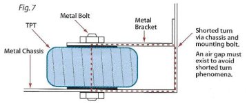
A metal band around the circumference of a toroid transformer is not a shorted turn, or a short of some other type. Note that metal covers for toroid transformers also totally surround the circumference of the transformer, and they do not short the transformer either.
This is a shorted turn, and must be avoided:
This is a shorted turn, and must be avoided:
Attachments
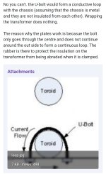
Just to be 100% sure there's no issue, the post @zman01 refers to an issue that appears to be different than a shorted turn.
The link he provides has someone describing a U-bolt as a bad option to secure a transformer as current can possibly be induced in the metal strap going around the circumference and grounded to the chassis.
I don't think that's an issue, and yet, I'm not 100% confident in that due to the post from soundchaser. Can the hive of minds confirm the strap will not cause an issue with any sort of interference or ground hum per the link stating that there is an issue. I'd feel bad if my 3D printed design for a transformer seat cause others issues.
Attachments
It is very hard to say...
The induced magnetic field in the toroid core is generated due to AC current running through the primary winding - the primary coil is wound around the metal core.
How much of a potential magnetic core material is that securing band presenting to the outside of two coils... is a question that needs answering. Could two coils (primary and secondary; the secondary is now loaded with the bridge rectifiers) have any ability to induce any magnetic field to their outside "peripheral" area..? Probably. How much? Very very (very) little. You could try to measure it... place a 0.1ohm resistor at one end of that strap, and then measure the AC voltage drop... see if you can detect anything.... I don't think you will...
Edit: now that I'm thinking about this measurements thingy... you'd need to rectify that (if any...) AC, and then measure it as DC... because the magnetic field would be changing polarity very quickly.
Ahh... my head hurts.
Edit No2: try to use a non-magnetic AND non-electrically conductive band... like straps used to secure loads on trucks... or similar.
Last edited:
I do not see an issue. The transformer mount that Jim (6L6) used in his build (https://www.diyaudio.com/community/threads/f5m-kit.408290/post-7628684) totally surrounds the transformer. The surrounding metal (as a belly band) may be beneficial as it provides some shielding against electromagnetic fields emanating from the transformer.
It was that exact post by 6L6 that actually inspired me to make a "diy" version using a 3D printed seat and the off the shelf pipe strap. The diy version is less than $6 if you have access to a 3D printer (capable of printing TPU) and buy the pipe straps on Amazon for ~2.50 each.
Build report:
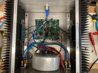
I took the M2X boards out of my 4RU home built chassis which uses Modushop 40X300X165mm heat sinks and put in my newly built F5M boards. I also decided to swap out the old CRC First Watt PS for the new thermistor design V1R1 supply. I happened to have 10 of the 15K uF 25V PS caps as used in the ACA mini as well as a slew of 6A thermistors. I needed to leave one cap out on each rail but it was easy to determine with a meter which caps on the new PCB are in the groups of 4 ahead of the output thermistor and cap. I was a bit concerned about the 25V cap rating but I'd been using 25V caps for years with the old supply and there was no voltage change going from the CRC to the CTC design. Both circuits produce +/-24.8 VDC rails. The transformer is an Antek AS-3218 and my home line voltage is at 123.4VAC.
Mouser was out of the 3/8" 3386P 1K trim pots with no equivalent available, so I decided to order 3362P 1/4" pots instead. Same pin spacing but mirror image circuit; full clockwise is 0 bias. Setting bias and DC offsets was touchy (glad I had two voltmeters) perhaps because of the shorter resistance track in the 1/4" pots. Still, I was able to get the channel-to-channel bias voltage drops within 0.002V of each other and the DC offsets in one channel at 0V and the other at 7mV, so I'm happy.
If I had it to do over, I'd get multiturn 3296W pots and bend the center pin to fit the PCB. Just double check which way to bend the middle pin to match the 3386P circuit footprint. The adjustment screw is above pin 1 so looking at the bottom of the pot with pin 1 north and pin 3 south, bend the middle pin 2 east.
I also tried alumina ceramic output device insulators for the first time. I bought some cheap Chinese ones on Amazon, spec'd at 1mm thick. They measured 0.98mm. I also used the relatively new Arctic MX-6 thermal compound. It's really thick and stiff, so I used a plastic scraper to get it down to a very thin layer. I ended up with about a 3 deg C delta between the transistor plastic body and the heat sink right next to the device. Seems pretty good but I can't remember what delta the Bergquist's had and unfortunately didn't remember to measure before I pulled the M2X boards.
With resistor bias voltage drop at 0.7 V even the 4RU tall sinks ran uncomfortably hot for me at around 60 deg C. This is with the caveat that I live in Arizona, it's 110 deg F outside and my minimally insulated shop building is 85 deg F with the AC running. I think the amp sounds reasonably good with the bias voltage at around 0.55V but will wait for cooler weather before pushing things. My F6 did not hit its sweet spot until I got it up to 0.575V.
I find that the F5M takes a long time for the bias to climb and stabilize, with voltage readings of around 0.48V after 15 - 20 minutes and taking well over an hour to climb up to 0.55V. Maybe it's my high ambient temperature. Both the F6 and the M2X seem to climb and stabilize much more quickly. Jury's still out on the sound, as I listened to the F5M in my small system and it was OK but need to see how it performs in a swap out with the F6 mid-hi amp in my big bi-amplified system.
Attachments
No need to bend the center pin, use 3296Y. Top adjustment screw and fits the board perfectly.

I said "fits the board perfectly" referring to pins vs. PCB holes. There will be some empty real state on the PCB.

Last edited:
After correcting my mistake (post 1704 w/pics) with J74 in incorrect spot, I'm powering up again via variac and getting very high rail voltage exceeding 26v on both channels before I get 70v on the variac measured off V+ and ground on the PS boards. Antek 4218 Trans, I should be around 25v on the rails I believe. Reading 17.8v from the rectifiers. All pots full CCW. Put new J74/K170's in after earlier mistake. Any ideas?
Difference between loaded and un-loaded rails is about 2V I believe. I would expect ~24V rails with a properly adjusted and functioning amplifier with a transformer that has 18V AC secondaries and the old bridge rectifiers.
- Home
- Amplifiers
- Pass Labs
- F5m kit