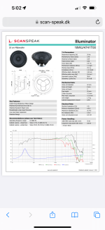
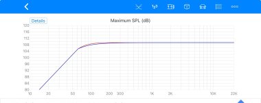
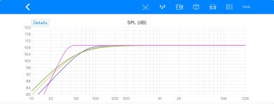
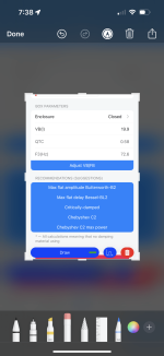
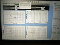
I ran a simulation in the smart phone App to give you an idea on the Illuminator 7 inch paper cone driver.
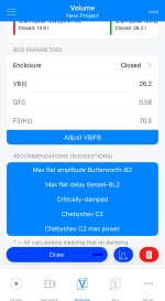
The max spl in the pass band is about it 109 db @ 1 metre. In the sealed alignments it’s limited to 70 hertz. If your intending to use it as a sealed mid bass driver the enclosure sizes are
Litres. QTC. F3
14. .707 68.4
26. .58 70.5
47. 0.5 75
A sonotube used for concrete forms with mdf end caps is an option l haves used as a sealed enclosure. The enclosure should be lightly filled with fibre glass insulation.
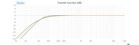
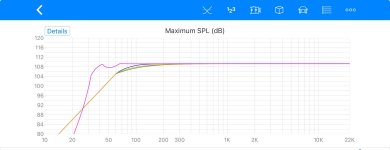
I also ran the bass reflex alignment. This driver has real potential. In a 34L enclosure the f3 is 35 hertz
What you could do is plug the rear port when you wish to run it with the SVS sub for home theatre.
The max spl in the pass band is about it 109 db @ 1 metre. In the sealed alignments it’s limited to 70 hertz. If your intending to use it as a sealed mid bass driver the enclosure sizes are
Litres. QTC. F3
14. .707 68.4
26. .58 70.5
47. 0.5 75
A sonotube used for concrete forms with mdf end caps is an option l haves used as a sealed enclosure. The enclosure should be lightly filled with fibre glass insulation.
I also ran the bass reflex alignment. This driver has real potential. In a 34L enclosure the f3 is 35 hertz
What you could do is plug the rear port when you wish to run it with the SVS sub for home theatre.
Attachments
-
 IMG_5233.jpeg122.3 KB · Views: 42
 -
 IMG_5241.jpeg105.8 KB · Views: 40
 -
 IMG_5240.jpeg165.9 KB · Views: 44
 -
 IMG_5239.png206 KB · Views: 40
 -
 IMG_5236.jpeg117 KB · Views: 47
 -
 IMG_5235.jpeg113 KB · Views: 34
 -
 IMG_5234.jpeg141.2 KB · Views: 40
 -
 IMG_5243.jpeg118.4 KB · Views: 38
 -
 IMG_5242.jpeg121.6 KB · Views: 39

Below is a link to a smart phone App with a data base of 5000 drivers to do hand held enclosure simulations.
This will help you sort through the functional performance aspects of different woofers. Performance limitations are easily verified.
It’s portable and includes a variety of curves to inform you about what a woofer will do in an enclosure. This includes various bass reflex and sealed alignments. Electrical EQ and other custom options are included in the free version. It’s better than Bassbox imo.
Joseph Crowe is becoming mature at testing drivers and has a true low distortion mic.
This link provides an understanding of objective measurement and subjective comments from someone who has tested a number of drivers.
I think the point of researching and taking on some of the subjective comments is that its common sense unless you are prepared to buy 1/2 dozen drivers to personally evaluate.
This is a premium aluminium woofer.
Not cheap either.
https://josephcrowe.com/blogs/news/purifi-ptt8-0x04-nab-02-8-aluminum-cone-woofer
Here the same driver profiled on the Voice Coil Test bench by Vance Dickason who has worked in the industry for 40 years.
https://audioxpress.com/article/test-bench-the-purifi-audio-ptt8-0x04-nab-02-8-aluminum-cone-woofer
Quote Vance Dickason:
“As with all the Test Bench reports I publish in Voice Coil magazine, I regret not being able to design these drivers into a system and do a proper subjective evaluation.”
Obviously a subjective evaluation matters
What's so special about the weird-looking surrounds of Purifi drivers subjectively? I think negative outcomes from the surround other than rubber ones reducing sensitivity are seldom mentioned during the discussions. But I am actually more worried about the WAF, lol, because it looks so weird, and my wife who usually don't care about looks of drivers may notice and complain...
I am kind of confused with the low side of FRs of the woofers I looked at, so want to understand those of Volt 8" ones, and then look at others. Do you agree that paper/pulp woofers sound more natural than others?
I ran a simulation in the smart phone App to give you an idea on the Illuminator 7 inch paper cone driver.
The max spl in the pass band is about it 109 db @ 1 metre. In the sealed alignments it’s limited to 70 hertz. If your intending to use it as a sealed mid bass driver the enclosure sizes are
Litres. QTC. F3
14. .707 68.4
26. .58 70.5
47. 0.5 75
A sonotube used for concrete forms with mdf end caps is an option l haves used as a sealed enclosure. The enclosure should be lightly filled with fibre glass insulation.
I also ran the bass reflex alignment. This driver has real potential. In a 34L enclosure the f3 is 35 hertz
What you could do is plug the rear port when you wish to run it with the SVS sub for home theatre.
Thank you very much again for your help and information. One thing I noticed interesting is that F3 goes up as the volume becomes larger, which seems a bit counter-intuitive. Maybe the sensitivity goes up at the cost of higher F3?
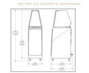
If it is really made in cylindrical and 18cm diameter is assumed for the cavity, the cross-sectional area is about 254cm^2 and requires 50+ cm depth. For a midbass covering from probably 150Hz, can the enclosure volume be smaller?
Sonotube is an interesting idea. Do you mean that your cylindrical speaker enclosure was made of hardened/compressed paper? Or you used concrete inside the sonotube? Is it sturdy and air-tight enough?
I am curious if 3-D printing it is a viable option. If it doesn't get too long, I'd like to have a tapered cavity which shouldn't be a big problem with 3-D printing. Maybe it should be done in multiple pieces and have to be put together seamlessly with glues?
Hopefully wool instead of fiber glass is also acceptable? I don't want to handle fiber glass too much, even wearing gloves.
With larger sealed box, the F6 and/or the F10 goes lower at the expense of the F3. But you can always EQ-it to the desired F3, F6 or whatever response you want as long as the system can handle it.One thing I noticed interesting is that F3 goes up as the volume becomes larger, which seems a bit counter-intuitive. Maybe the sensitivity goes up at the cost of higher F3?
Last edited:
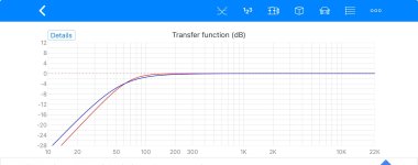
The lower QTC sealed enclosure follows the high pass electrical filter.
The effect is a more gradual curve that starts at a higher frequency. It does go a bit lower too.
Yes theses tubes are stiff cardboard quite strong. I would make a disk out of plywood.
Make it somewhat larger than the driver so you can carve out a round over. That way you can use the largest sono tube
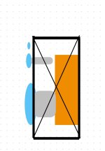
You could have a rectangle box shape further back that is not visible from the front
See my attached sketch.
The Surrounds on the Purifi are strange but they apparently work.
My suggestion is not to paint yourself into a corner with the industrial design until you have a mock up that works as it should acoustically.
I recommend that you start to realise the impact of different baffles and driver locations on baffles.
Referring the the link below the is an Excel spreadsheet.
Go through it and model your woofer trying some simple baffles
http://audio.claub.net/software/jbabgy/BDBS.html
The effect is a more gradual curve that starts at a higher frequency. It does go a bit lower too.
Yes theses tubes are stiff cardboard quite strong. I would make a disk out of plywood.
Make it somewhat larger than the driver so you can carve out a round over. That way you can use the largest sono tube
You could have a rectangle box shape further back that is not visible from the front
See my attached sketch.
The Surrounds on the Purifi are strange but they apparently work.
My suggestion is not to paint yourself into a corner with the industrial design until you have a mock up that works as it should acoustically.
I recommend that you start to realise the impact of different baffles and driver locations on baffles.
Referring the the link below the is an Excel spreadsheet.
Go through it and model your woofer trying some simple baffles
http://audio.claub.net/software/jbabgy/BDBS.html
Attachments
Last edited:
This is an interesting project to look for clues on how to approach different challenges
https://www.diyaudio.com/community/threads/the-elsinore-project-thread.97043/
https://www.diyaudio.com/community/threads/the-elsinore-project-thread.97043/
For a midbass covering from probably 150Hz, I am curious if 3-D printing it is a viable option. If it doesn't get too long, I'd like to have a tapered cavity which shouldn't be a big problem with 3-D printing. Maybe it should be done in multiple pieces and have to be put together seamlessly with glues?
Hopefully wool instead of fiber glass is also acceptable? I don't want to handle fiber glass too much, even wearing gloves.
The answer on making the enclosure smaller for 150 hertz crossover point is no.
1. I recommend you use the QTC 0.707 enclosure if a smaller enclosure is preferred.
On www there are explanations of the effects of damping materials.
2. You will also need to look at that diffraction model. Set up the model with baffle (square) the same or lager diameter of the driver and apply round overs.
Locate the driver centrally on the baffle in input the distance from the ground.
I would assess several different baffles and positions from the ground so that you become more familiar with the impact on the responses.
2. My recommendation is to stick with a stuffing available from Parts Express before considering alternatives.
3. As mentioned previously set up up a mock up of the system with the aim of ascertaining the optimal crossover transfer function and x x my EQ required.
Note it might be necessary to look at an alternative driver location and distance pending the crossover network and initial subjective assessment.
4. Commence development of the industrial design.
With the Volt drivers you need to have a clear plan of the specific operating range and the other associated drivers before proceeding.
They are designed for near field monitors and larger multi way (sub bass, midrange domes) used by Quested and PMC.
What are you using for the 20-150 hertz range?
What are you using for the 150-800 hertz region?
How is that going to fit in your other ideas ?
They are designed for near field monitors and larger multi way (sub bass, midrange domes) used by Quested and PMC.
What are you using for the 20-150 hertz range?
What are you using for the 150-800 hertz region?
How is that going to fit in your other ideas ?
While not wishing to cross your concept of using cylinders as you are starting to realise the volume requirements of a woofer can become a problem.
Realising this and your desire to evolve your project another approach may be to your advantage.
The width limitations of your project and the desire for a mid bass driver creates a cabinet design problem requiring two independent chambers.
Two such chambers can efficiently be incorporated into a rectangular shaped low frequency enclosure.
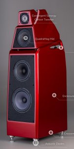
The satellite enclosure sits atop of the low frequency enclosure. With this enclosure you can apply 3D printed diffraction control. Notably for the tweeter. The satellite can be re configurated with different drivers.
I see the low frequency enclosure as a more matter of fact design exercise based around a driver selection to smoothly cover from 30 hertz to 800 hertz. The design can be easily predicted in a simulation.
Issues such as baffle step can be engineered out quite effectively using two drivers with overlapping ranges.
I chose a 25cm 10 or inch driver for the low woofer because needs to do more work than the 18cm mid bass driver. A 25cm woofer is also more efficient and will produce low distortion all things being equal. The additional width can be an aspect of the industrial design.
The head or satellite may need several revisions and you have the flexibility to do this experimenting with alternative diffraction control shapes.
I think overall you would find such an approach much easier to assemble and give you at least one known aspect to the overall design. Anchoring the design with the bass will make sorting out the system much less complicated.
Realising this and your desire to evolve your project another approach may be to your advantage.
The width limitations of your project and the desire for a mid bass driver creates a cabinet design problem requiring two independent chambers.
Two such chambers can efficiently be incorporated into a rectangular shaped low frequency enclosure.
The satellite enclosure sits atop of the low frequency enclosure. With this enclosure you can apply 3D printed diffraction control. Notably for the tweeter. The satellite can be re configurated with different drivers.
I see the low frequency enclosure as a more matter of fact design exercise based around a driver selection to smoothly cover from 30 hertz to 800 hertz. The design can be easily predicted in a simulation.
Issues such as baffle step can be engineered out quite effectively using two drivers with overlapping ranges.
I chose a 25cm 10 or inch driver for the low woofer because needs to do more work than the 18cm mid bass driver. A 25cm woofer is also more efficient and will produce low distortion all things being equal. The additional width can be an aspect of the industrial design.
The head or satellite may need several revisions and you have the flexibility to do this experimenting with alternative diffraction control shapes.
I think overall you would find such an approach much easier to assemble and give you at least one known aspect to the overall design. Anchoring the design with the bass will make sorting out the system much less complicated.
Attachments
I thought that OP wanted to follow the Gallo's way...and Macka just followed the box enclosure style.
So there are two opposing treads and I much prefer the first thread...er...Trend, which is naked. Conflicting with the cylinder shape which offers no baffle to calculate radiation and adds the problem of internal aerodynamic which seems that might be mitigated by tapering in some cases where the magnitude is not big (midrange) or take advantage of mass loading of the air column where long wavelengths (the 1/4 wave...) play, so bass.
Wood for boxes is out of style, it follows
Attaching and suspending the cylinders is the new challenge
It’s an alternative because the volume of a cylinder is not possibly. That was previously outlined.
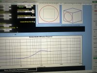
I ran the Diffraction and Baffle Simulator 1.3 today. Unfortunately the results aren’t promising.
Using a square 8” baffle with a 2” radius the baffle has a -3 db point at 400 hertz and -6 at 100 hertz. The round over had no effect on the baffle step. Only on the diffraction bump in the pass band.
Looking at the combined Baffle Diffraction/ Room Augmented with the driver located 24” above the floor and 14” from the rear wall there is a 5 db trough below 400 hertz dipping to -7 db at 120 hertz.
The impact: Even with electrical EQ the driver and or the power will quickly run out of headroom attempting to operate with a smooth flat response down to 150 hertz. Keeping in mind the sealed mid bass enclosure has a -3 db point of about 70 hertz the baffle step decimates the system working correctly.
The idea of a mid bass woofer operating in a separate pass band and is not going to be satisfactory because the reinforcement is required from both drivers above 250 hertz.
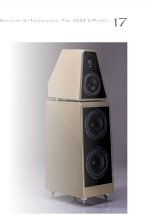
The Solution: Commercial loudspeaker manufacturers of tower loudspeakers are well aware of this scenario. The solution is to employ additional woofers in a vertical layout on these narrow baffles. Each woofer adds +3 db acoustic output. By staggering the low pass crossover points a smooth response can be obtained.
Kef, Focal, B&W and Monitor Audio all use this technique successfully with their tower systems. The other benefit is much low bass driver distortion due the increased cone area. More cone area surpasses X max with overall displacement. 2 x cone area equals 1/4 of the cone movement.
The idea of the cylinder chamber could still be applied to the dome midrange and tweeter.
I suggestion to the TO is to find a commercial design that has similarities to his own ideas and attempt to clone that design. For example look through Zaph’s and Troels designs. These designs have been proven.
Otherwise you are shooting in the dark with a narrow baffle design from scratch. Even with a dsp crossover and EQ the underlying issue and the stress it will put the drivers under wont magically go away. I mean this respectfully to avoid disappointment.
https://trueaudio.com/st_diff1.htm
https://www.diyaudio.com/community/...ompinsation-for-a-sphere.105748/#post-1262324
https://www.diyaudio.com/community/...ompinsation-for-a-sphere.105748/#post-1262459
I have attached some references above e for different baffle and enclosure shapes.
There will be those that disagree. But the facts don’t lie. Particularly when commercial designs point the issue and a solution. Unfortunately the baffle step problem is there. As l hinted at earlier in the thread the best way around this issue is to stack two more more drivers vertically.
There are plenty of very good 6 1/2 inch woofers from Seas, Scanspeak and Peerless to name a few that will function perfectly in this situation.
The link to Joe’s design is an excellent example of the above principles.
Using a square 8” baffle with a 2” radius the baffle has a -3 db point at 400 hertz and -6 at 100 hertz. The round over had no effect on the baffle step. Only on the diffraction bump in the pass band.
Looking at the combined Baffle Diffraction/ Room Augmented with the driver located 24” above the floor and 14” from the rear wall there is a 5 db trough below 400 hertz dipping to -7 db at 120 hertz.
The impact: Even with electrical EQ the driver and or the power will quickly run out of headroom attempting to operate with a smooth flat response down to 150 hertz. Keeping in mind the sealed mid bass enclosure has a -3 db point of about 70 hertz the baffle step decimates the system working correctly.
The idea of a mid bass woofer operating in a separate pass band and is not going to be satisfactory because the reinforcement is required from both drivers above 250 hertz.
The Solution: Commercial loudspeaker manufacturers of tower loudspeakers are well aware of this scenario. The solution is to employ additional woofers in a vertical layout on these narrow baffles. Each woofer adds +3 db acoustic output. By staggering the low pass crossover points a smooth response can be obtained.
Kef, Focal, B&W and Monitor Audio all use this technique successfully with their tower systems. The other benefit is much low bass driver distortion due the increased cone area. More cone area surpasses X max with overall displacement. 2 x cone area equals 1/4 of the cone movement.
The idea of the cylinder chamber could still be applied to the dome midrange and tweeter.
I suggestion to the TO is to find a commercial design that has similarities to his own ideas and attempt to clone that design. For example look through Zaph’s and Troels designs. These designs have been proven.
Otherwise you are shooting in the dark with a narrow baffle design from scratch. Even with a dsp crossover and EQ the underlying issue and the stress it will put the drivers under wont magically go away. I mean this respectfully to avoid disappointment.
https://trueaudio.com/st_diff1.htm
https://www.diyaudio.com/community/...ompinsation-for-a-sphere.105748/#post-1262324
https://www.diyaudio.com/community/...ompinsation-for-a-sphere.105748/#post-1262459
I have attached some references above e for different baffle and enclosure shapes.
There will be those that disagree. But the facts don’t lie. Particularly when commercial designs point the issue and a solution. Unfortunately the baffle step problem is there. As l hinted at earlier in the thread the best way around this issue is to stack two more more drivers vertically.
There are plenty of very good 6 1/2 inch woofers from Seas, Scanspeak and Peerless to name a few that will function perfectly in this situation.
The link to Joe’s design is an excellent example of the above principles.
Attachments
Hi,
That's why we emphasised to first study acoustical design.
And why i said 'large'/'wide' box are not solution to dismiss to early either.
I don't see baffle step to be 'an issue', as diffraction ( in fact bsc is a kind of diffraction) it'll be present in 99% of cases ( only inwall change the situation for both bsc and diffraction) and should be taken into account since first design steps.
I find funny we see bsc the other side around of each other pov: for me baffle step outcome is a gain in the high end ( rather than a loss in low end) because box dimensions focus sound emited toward a lower radiated area. I usually treat it the same way: an 4 octave wide high shelf whose center freq is more or less centered around 115/ baffle width in meter, attenuating high frequency.
From a psychoacoustic pov and with real life implementation It have merits vs boosting low end.
I would not be too much confident on commercial offer to find answers: there is few brands which communicate about 'important' parameters and their design choices in honest manner.
Anyway if not clearly stated which choices have been made and why, the only way to find if an approach is really valid or not is by simulation and reverse engineering a design.
I thought that OP wanted to follow the Gallo's way...and Macka just followed the box enclosure style.
So there are two opposing treads and I much prefer the first thread...er...Trend, which is naked. Conflicting with the cylinder shape which offers no baffle to calculate radiation and adds the problem of internal aerodynamic which seems that might be mitigated by tapering in some cases where the magnitude is not big (midrange) or take advantage of mass loading of the air column where long wavelengths (the 1/4 wave...) play, so bass.
Wood for boxes is out of style, it follows
Attaching and suspending the cylinders is the new challenge
I disagree with the 'cylinder offer no baffle part' of your comment but i might not get what you mean? Could you clarify that point please? As i already played with 'tube loaded drivers' i have my own observation about it but don't want to bias your answer as i might have been lost in translation...
Otherwise nice summary! I agree if pipe are used then Transmission Lines should be contemplated.
Someone previously talked about Dagger approach, brilliant idea imho.
Closed lines can be worth a look too, they can be configured to kill backwave from box/driver and could bring 'dipoleness' to sound ( less 'boxy' sound coloration - i hate using words as 'boxy' as it could potentially describe so many things... but you got the idea). Can works wonder on low/mid, mid. Even aperiodic should be thought about imho especially if paired with a dome mid which offer low level of distortion.
Lol,
Ok just took a look: nah... not Gallo: Cabasse!
We have a long history of ball shaped loudspeakers in France: in 60's Elipson, since Cabasse used the concept a lot. Last rev is 'La Sphere', an 'ultimate' ball shaped loudspeaker: 4 (coaxial!) ways, dsp powered.... not easy to clone... but nice ideas ( the low way radiate through slot loaded... implementing passive hp and lowering distortion. I bet they are located at a place where they don't need delay to compensate for acoustic center - like mid driver are located on a meh but backward ... if you see what i mean?).
https://www.cabasse.com/fr/la-sphere-2/
Sorry for my late response. A lot of great inputs but some chores for the weekend....
Slowest rolloff would be the best standalone, but there will a double-woofer module below, so rapid roll-off is not bad if it doesn't have a overshoot peak. I was thinking of the woofer-midbass crossover around 150Hz. I probably won't be able to use a steep linear-phase FIR filter due to the excessive latency, so need to rely on mechanical crossover and LR4 or LR8 or minimum-phase FIR filter(little latency problem) that I am not familiar with designing one yet....
It sounds great. I am looking at 3-D printing option for the cap, too.
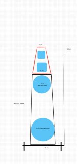
I was thinking exactly the same, rectangular in the back, and cylindrical in the front! Or maybe something looking like this with no top cylinder? Will this shape be effective in addressing the baffle step/diffractions? Or maybe the FR of this midbass doesn't concern such things of the diameter similar to the drivers?

As you wrote somewhere donw in the later reply, I agree with you that I should settle down on the woofers and the cabinets, especially dimensions. As many agreed, this must be the most challenging part of the mechanical design. Let me get back with what I can come up with after digesting the inputs.
The lower QTC sealed enclosure follows the high pass electrical filter.
The effect is a more gradual curve that starts at a higher frequency. It does go a bit lower too.
Slowest rolloff would be the best standalone, but there will a double-woofer module below, so rapid roll-off is not bad if it doesn't have a overshoot peak. I was thinking of the woofer-midbass crossover around 150Hz. I probably won't be able to use a steep linear-phase FIR filter due to the excessive latency, so need to rely on mechanical crossover and LR4 or LR8 or minimum-phase FIR filter(little latency problem) that I am not familiar with designing one yet....
Yes theses tubes are stiff cardboard quite strong. I would make a disk out of plywood.
It sounds great. I am looking at 3-D printing option for the cap, too.
Make it somewhat larger than the driver so you can carve out a round over. That way you can use the largest sono tube
You could have a rectangle box shape further back that is not visible from the front
I was thinking exactly the same, rectangular in the back, and cylindrical in the front! Or maybe something looking like this with no top cylinder? Will this shape be effective in addressing the baffle step/diffractions? Or maybe the FR of this midbass doesn't concern such things of the diameter similar to the drivers?
See my attached sketch.
The Surrounds on the Purifi are strange but they apparently work.
My suggestion is not to paint yourself into a corner with the industrial design until you have a mock up that works as it should acoustically.
I recommend that you start to realise the impact of different baffles and driver locations on baffles.
Referring the the link below the is an Excel spreadsheet.
Go through it and model your woofer trying some simple baffles
http://audio.claub.net/software/jbabgy/BDBS.html
As you wrote somewhere donw in the later reply, I agree with you that I should settle down on the woofers and the cabinets, especially dimensions. As many agreed, this must be the most challenging part of the mechanical design. Let me get back with what I can come up with after digesting the inputs.
I thought that OP wanted to follow the Gallo's way...and Macka just followed the box enclosure style.
Not exactly 🙂. I think cylinders and spheres are different enough, though I guess the Bessel internal acoustic function of both approaches gives us some advantage over rectangular ones.
So there are two opposing treads and I much prefer the first thread...er...Trend, which is naked. Conflicting with the cylinder shape which offers no baffle to calculate radiation and adds the problem of internal aerodynamic which seems that might be mitigated by tapering in some cases where the magnitude is not big (midrange) or take advantage of mass loading of the air column where long wavelengths (the 1/4 wave...) play, so bass.
Wood for boxes is out of style, it follows
Attaching and suspending the cylinders is the new challenge
I had realized that just stacking, especially for lighter tweeter/midhigh, is probably not robust. I think I will have to make something sticking out and the matching hole to avoid too much drift and easy alignment. Any better idea?
- Home
- Loudspeakers
- Multi-Way
- 4-way instead of 3-way?