The bigger capacitor is not only a bad tolerance but also a big dimension. It is impossible for near tonearm placing like that https://photos.app.goo.gl/UX72m8GxKPmx4CGu7 https://photos.app.goo.gl/FzSoKajQzW7MJ6EZAI will get larger DC feedback capacitors once I have enough items to place
The tolerance of DC feedback capacitors does not matter. The pre-amp and turntable are two shelves apart.
Ed
Ed
I don’t think so Ed. Response is response.The "+1" error may seem small, but I believe it is the reason why passive EQ seems to show less record surface noise than active non-inverting EQ.
Ed

Bonsai - The error increasing in the positive direction with frequency is something that I would rather not have.
Ed
Ed
Why not use C3-R5 too to get a steeper slope? Provided that you have control over the impedance of the next stage, if e.g. with the shown R5=33k you make C3=1u, you get an extra 8dB attenuation @2Hz (see attached) while still keeping the 20-20k FR within the same +/- 0.13dB. Just an idea.
Cheers,
Cabirio
I didn't do that because I assumed the load impedance to be some unknown value greater than or equal to 10 kohm.
Besides, you can't make a Butterworth filter with two negative real poles (two first-order sections) unless you cover a pole with a zero, which would spoil its effect. It's not a big deal, because what you can do is make a kind of quasi-Butterworth response. You then optimize the quality factor and natural frequency of the loop to give the flattest possible response together with the two negative real poles.
I need to check if I calculated it correctly, but if I did, this is the result for a high-pass:
Two first-order high-pass sections with the same cut-off frequency
One second-order high-pass section with Q = 1/sqrt(2 - 2/sqrt(3)) ~= 1.087663874 and a natural frequency of the fourth-order root of three (1.316074013) times the cut-off frequency of the first-order high-pass sections
The result for a low-pass is the same, except that the high-pass sections become low-pass sections and the natural frequency of the second-order section has to be 1/1.31607401... times that of the first-order sections.
Ed, its normally below unity gain and easily compensated for with a post filter. The advantages of all active are superb overload capability, and generally better noise in most cases. They are more difficult to design because of the interaction of the poles and zeroes (a point Lipshitz makes in his paper) but the extra effort IMV is worth it. My X-Altra MC/MM achieves>30 dB overload from <20 Hz through to 50 kHz with conformance of +-0.15 dB 20Hz-20 KHz and its still within 0.8 dB at 50 kHz.Bonsai - The error increasing in the positive direction with frequency is something that I would rather not have.
Ed
Let's not pollute Marcel's excellent thread with this stuff though.
Peace.
I'm refering to the non-inverting configuration in his paper.Lipshitz gives extensive formulae and a detailed procedure for designing RIAA stages analytically rather than iteratively, and states that this is the whole point of his paper.
The part about a post low-pass filter only applies to series feedback systems, not all active systems.
I have his design methodology and his equations in a spreadsheet on my website. You start by entering a resistor value and the spreadsheet will then calculate the other values - but you have to iterate the value a few times to get the correct response with the selected components. See the X-Altra MC/MM for the finished performance results.
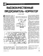
To avoid manual iteration, I use the Microcap 12 "Optimize" function to calculate and optimize my 5-tau T-chain. At a picture attached approximations are "Neumann\LCRin"=R13C7, 75us=R12C7, 318us=R12R14C9, 3180us=R15C9, 7950us=R14C8. Since the Lipshitz calculations are theoretical and not for my T-shaped circuit, I set automatic optimization in Microcap12 for full circuit, requiring that the resulting frequency response of my phono preamp exactly match the standard frequency response values of the RIAA. In just a few seconds, I get the calculated values of all the resistors and capacitors for a real circuit with general feedback and finite open-loop stage gains. All that remains is to select the closest values of resistors and capacitors from the E48 or E96... In my opinion, this technique is impeccable for any configuration of the frequency response correction circuit, active or passive, inverting or non-inverting, single-stage or multi-stage.but you have to iterate the value a few times to get the correct response
Attachments
Last edited:
probably you meant not "driven by" but "@ transimped input" ?passive EQ driven by a transconductance amplifier has the same overload margin as active EQ
Nick - I meant what I wrote:
VCCS -> RC network -> VCVS
You are thinking about its dual:
VCVS -> RL network -> ICVS
Ed
VCCS -> RC network -> VCVS
You are thinking about its dual:
VCVS -> RL network -> ICVS
Ed
Good, understand. I use almost the same principle with transadmittance output stage (see V5 as VCCS and RIAA RC network to gate of V2 at my circuit diag @ message #49) with overall negative feedback to input stage. All the best of both active and passive worlds in a one circuit.I meant what I wrote:
VCCS -> RC network -> VCVS
This is a common but unfortunate arrangement. Because of the large (but not at all necessary with this right arrangement close to the tonearm - https://photos.app.goo.gl/UX72m8GxKPmx4CGu7 ) capacity of the interconnect cable.The pre-amp and turntable are two shelves apart.
Not quite. Your circuit needs the additional low-pass filter on the output to fix the +1 error.Nick Sukhov said:All the best of both active and passive worlds in a one circuit.
Beyond that, both active and passive EQ need an extreme of some parameter - gain in the case of active EQ, and impedance (or admittance) in the case of passive EQ. Both approaches can be made to work well.
Ed
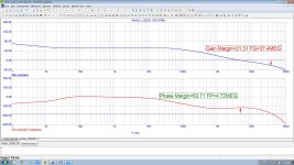
Yes, and my transadmittance circuit has almost constant loop gain from infra to ultra frequencies, see attach. No problems with stability at HF, no problems with THD at LF, no problems with overload margins, no problems with Miller ... etc.Beyond that, both active and passive EQ need an extreme of some parameter
Attachments
Version meant for a dual supply and for a cut-off frequency of about 16 Hz, assuming both E24 and E96 resistors are acceptable:

Like before, C5, C6, C8, R8 and R12 need to be accurate to get accurate RIAA correction, the other resistors and capacitors mostly affect the subsonic filter response (and R6 and C4 the cartridge loading).
Like before, C5, C6, C8, R8 and R12 need to be accurate to get accurate RIAA correction, the other resistors and capacitors mostly affect the subsonic filter response (and R6 and C4 the cartridge loading).
Last edited:
Marcel, how does the click response (mistracking) look like? Because of the higher order HP filter used.
- Home
- Source & Line
- Analogue Source
- Single-stage active RIAA correction with second- or third-order Butterworth high-pass included