The Radford SC-22 valve preamp has a similar network around the RIAA network, although it goes to ground rather than the inverting input.
Last edited:
that SC22 network is indeed part of the rumble filter adjust potentiometer. The manual writes "a steep 35c/s rumble filter". UK language uses cycles instead of german Hertz.
Last edited:
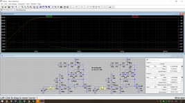
I've run the feedback network of the Radford HD250 through LINDA, a pole-zero extraction program. It found this:
* Feedback network of a Radford HD250
R9 1 2 3300
C56 2 3 94E-9
C9 1 3 33E-9
R10 1 3 22E3
R12 1 4 8200
C10 4 0 1.5E-6
R11 4 5 10E3
C78 5 0 80E-6
R8 5 3 47
.source 1 0 V
.detector 3 0 V
.plex
.end
Simulation results:
DCgain = 1.000
Number of poles: 4 Number of zeros: 4
n pole n Real part Imaginary part
[rad/s] [rad/s] [rad/s]
1 -655.613 E 3 1 -13.454 E 3
2 -3.182 E 3 2 -499.261
3 -1.247 3 -122.835 -206.009
4 -148.535 4 -122.835 206.009
PLEX compatible file written to: D:\HD250_1.PLX
Time used for reading circuit and calculation: 00:00:03
JOB SUCCESFULLY TERMINATED
In case of infinite loop gain, the closed-loop transfer should be the reciprocal of the feedback network transfer, so all poles become zeros and all zeros poles. That is, for an ideal RIAA correction amplifier, the zeros of the feedback network should be -1/(3.18 ms) = -314.465408... rad/s and -1/(75 μs) = -13333.3333... rad/s and the pole -1/(318 μs) = -3144.65408... rad/s. With a second-order high-pass included, one would expect two extra feedback network poles close to 0 and a complex zero pair.
The complex zero pair exists, but there is only one pole close enough to 0. There is a zero quite close to -13333.3333... rad/s and a pole close to -3144.65408... rad/s, but the zero that was expected at -314.465408... rad/s is shifted all the way to -499.261 rad/s.
When you short out C7 and C8, it gets close to a conventional RIAA amplifier:
* Feedback network of a Radford HD250
R9 1 2 3300
C56 2 3 94E-9
C9 1 3 33E-9
R10 1 3 22E3
R12 1 4 8200
C10 4 0 1.5E-6
R11 4 5 10E3
*C78 5 0 80E-6
V1 5 0 0
R8 5 3 47
.source 1 0 V
.detector 3 0 V
.plex
.end
Simulation results:
DCgain = 2.132 E -3
Number of poles: 3 Number of zeros: 3
n pole n zero
[rad/s] [rad/s]
1 -147.967 1 -13.454 E 3
2 -655.351 E 3 2 -330.047
3 -3.178 E 3 3 -147.967
PLEX compatible file written to: D:\HD250_2.PLX
Time used for reading circuit and calculation: 00:00:03
JOB SUCCESFULLY TERMINATED
Note that pole 1 and zero 3 cancel.
I don't know what the idea behind the Radford HD250 is, and it could very well be a very good design, but they don't seem to try and approximate a combination of a RIAA correction and a Butterworth high-pass.
* Feedback network of a Radford HD250
R9 1 2 3300
C56 2 3 94E-9
C9 1 3 33E-9
R10 1 3 22E3
R12 1 4 8200
C10 4 0 1.5E-6
R11 4 5 10E3
C78 5 0 80E-6
R8 5 3 47
.source 1 0 V
.detector 3 0 V
.plex
.end
Simulation results:
DCgain = 1.000
Number of poles: 4 Number of zeros: 4
n pole n Real part Imaginary part
[rad/s] [rad/s] [rad/s]
1 -655.613 E 3 1 -13.454 E 3
2 -3.182 E 3 2 -499.261
3 -1.247 3 -122.835 -206.009
4 -148.535 4 -122.835 206.009
PLEX compatible file written to: D:\HD250_1.PLX
Time used for reading circuit and calculation: 00:00:03
JOB SUCCESFULLY TERMINATED
In case of infinite loop gain, the closed-loop transfer should be the reciprocal of the feedback network transfer, so all poles become zeros and all zeros poles. That is, for an ideal RIAA correction amplifier, the zeros of the feedback network should be -1/(3.18 ms) = -314.465408... rad/s and -1/(75 μs) = -13333.3333... rad/s and the pole -1/(318 μs) = -3144.65408... rad/s. With a second-order high-pass included, one would expect two extra feedback network poles close to 0 and a complex zero pair.
The complex zero pair exists, but there is only one pole close enough to 0. There is a zero quite close to -13333.3333... rad/s and a pole close to -3144.65408... rad/s, but the zero that was expected at -314.465408... rad/s is shifted all the way to -499.261 rad/s.
When you short out C7 and C8, it gets close to a conventional RIAA amplifier:
* Feedback network of a Radford HD250
R9 1 2 3300
C56 2 3 94E-9
C9 1 3 33E-9
R10 1 3 22E3
R12 1 4 8200
C10 4 0 1.5E-6
R11 4 5 10E3
*C78 5 0 80E-6
V1 5 0 0
R8 5 3 47
.source 1 0 V
.detector 3 0 V
.plex
.end
Simulation results:
DCgain = 2.132 E -3
Number of poles: 3 Number of zeros: 3
n pole n zero
[rad/s] [rad/s]
1 -147.967 1 -13.454 E 3
2 -655.351 E 3 2 -330.047
3 -3.178 E 3 3 -147.967
PLEX compatible file written to: D:\HD250_2.PLX
Time used for reading circuit and calculation: 00:00:03
JOB SUCCESFULLY TERMINATED
Note that pole 1 and zero 3 cancel.
I don't know what the idea behind the Radford HD250 is, and it could very well be a very good design, but they don't seem to try and approximate a combination of a RIAA correction and a Butterworth high-pass.
Why not use C3-R5 too to get a steeper slope? Provided that you have control over the impedance of the next stage, if e.g. with the shown R5=33k you make C3=1u, you get an extra 8dB attenuation @2Hz (see attached) while still keeping the 20-20k FR within the same +/- 0.13dB. Just an idea.
Cheers,
Cabirio
Cheers,
Cabirio
Attachments
In the 1979 Lipshitz paper he explains that with an all active scheme it’s not possible to get accurate RIAA conformance at the top end of the audio band without a post low pass filter - usually set at a few octaves higher so 100-200 kHz. I calculate the main EQ components and then usually tweak the post filter cut off in LTspice to get the response to within +-0.15 dB. Measurements with the QA401 inverse RIAA function show conformance is usually very good. In any event, the error without the post filter is never more than about 0.5 dB anyway.
The Lipshitz active EQ equations are very accurate but the terms are all coupled. So you cannot just calculate the R and C from the time constants because they all interact with each other (unlike passive schemes that don’t have this problem). So, the process is iterative and you have to converge in on the correct values.
The Lipshitz active EQ equations are very accurate but the terms are all coupled. So you cannot just calculate the R and C from the time constants because they all interact with each other (unlike passive schemes that don’t have this problem). So, the process is iterative and you have to converge in on the correct values.
Last edited:

If we shift the formation of the 3.18 ms pole to the middle of the T-shaped correction circuit, as in my 1981 phono stage, then the problem of the multi-microfarade capacitor is eliminated. I used R14=16k and C8=0.47uF to create 7950us , see here https://archive.radio.ru/web/1981/03/037/ .The disadvantage of using C8 for the first RIAA pole is that C8, which has a relatively large value, needs to be accurate to get an accurate first RIAA pole.
Lipshitz gives extensive formulae and a detailed procedure for designing RIAA stages analytically rather than iteratively, and states that this is the whole point of his paper.So you cannot just calculate the R and C from the time constants because they all interact with each other
The part about a post low-pass filter only applies to series feedback systems, not all active systems.
Last edited:
I was unaware of the Lipshitz paper at the time. I switched to passive EQ because I could not get enough gain to make active EQ accurate.
Ed
Ed
In the 1979 Lipshitz paper he explains that with an all active scheme it’s not possible to get accurate RIAA conformance at the top end of the audio band without a post low pass filter - usually set at a few octaves higher so 100-200 kHz.
There is the + 1 term, as in the voltage gain equation Z1/Z2 + 1. The gain drops to 1 rather than 0 for high frequencies causing an error, but as it is about 0.04 dB to 0.05 dB at 20 kHz for a midband gain of 100, I usually don't bother correcting it.
You can partly correct it by making the input resistance a bit too low, thereby damping the resonance of the cartridge and the cable and amplifier input capacitance a bit more. In fact, the circuit of post #1 will have slightly too little treble because of its too low input resistance.
The "+1" error may seem small, but I believe it is the reason why passive EQ seems to show less record surface noise than active non-inverting EQ.
Ed
Ed
you are mistaken in your confidence, because the weighted noise of a phono record has a maximum at mid and low audio frequencies, while "the 1 or 0 at higher frequencies" in message #32 are at tens of kilohertz.I believe it is the reason why passive EQ seems to show less record surface noise than active non-inverting EQ
Last edited:
About 200 kHz when the gain at 1 kHz is 100. The Bode asymptote is horizontal until 2122 Hz and then drops at 20 dB/decade, so the gain should (but doesn't with the + 1 term) cross unity somewhere around 2122 Hz times the gain at 1 kHz. That means that the error at 20 kHz gets larger when the midband gain is lower.
Maybe Ed measures it unweighted over a large bandwidth (>> 20 kHz)?
Maybe Ed measures it unweighted over a large bandwidth (>> 20 kHz)?
Last edited:
I also measure unweighted over 48 kHz BWMaybe Ed measures it unweighted over a large bandwidth (>> 20 kHz)?
I don't hear record surface noise as much as I once did. It is just an observation. Of course, the EQ is one of 20 things that have changed in the intervening years.
Ed
Ed
By the way, it's off topic, but passive RIAA calculations tend to get complicated when there is AC coupling involved.
https://www.diyaudio.com/community/...a-calculator-formula-help.401437/post-7439558
https://www.diyaudio.com/community/...eamp-phono-section-slp-70.407297/post-7557077
https://www.diyaudio.com/community/...a-calculator-formula-help.401437/post-7439558
https://www.diyaudio.com/community/...eamp-phono-section-slp-70.407297/post-7557077
but you say a nice idea "end up with a reverse RIAA network in the DC servo" 👍By the way, it's off topic, but
I will get larger DC feedback capacitors once I have enough items to place an order. The error is small enough that it went unnoticed until Marcel pointed it out. 🙂
Ed
Ed
- Home
- Source & Line
- Analogue Source
- Single-stage active RIAA correction with second- or third-order Butterworth high-pass included