How is this even possible?
They either broke every known Electrical Engineering Law or there is a Solid State Current Amp at its output and they're flat out lying.
https://acusticaapplicata.com/en/product/alieno-amplifier-250-ltd/
They either broke every known Electrical Engineering Law or there is a Solid State Current Amp at its output and they're flat out lying.
https://acusticaapplicata.com/en/product/alieno-amplifier-250-ltd/
Attachments
Last edited:
Search with google: current multiplier.
Whatever claims the marketing BS, it's hybrid.
p.s.
Some reading material to learn similar structures:
https://groupdiy.com/threads/tube-otl-and-zotl-amps.83620/
Whatever claims the marketing BS, it's hybrid.
p.s.
Some reading material to learn similar structures:
https://groupdiy.com/threads/tube-otl-and-zotl-amps.83620/
Last edited:

That lower chassis with the big heat sinks may give you a clue to where the 100 peak Amps come from.
Probably a current summing output stage with the voltage determined by the tube amp,
and with the current determined by the SS amp (err, power supply). Well, it DOES supply power, doesn't it?
Probably a current summing output stage with the voltage determined by the tube amp,
and with the current determined by the SS amp (err, power supply). Well, it DOES supply power, doesn't it?
How about using 300B as switchers. Not efficient by todays standards, but should get 2x to 3X the power versus using the 300B in linear mode.
You will need to do Lots of design work to get the amplifier to perform properly.
Tube switcher amplifiers, anybody?
No, . . . not to step on David Berning's amplifier designs.
You will need to do Lots of design work to get the amplifier to perform properly.
Tube switcher amplifiers, anybody?
No, . . . not to step on David Berning's amplifier designs.
The Berning amps do pass the signal through a small HF transformer, although the signal modulates a fixed HF carrier wave.
Each amp is modulated power supply. 😁
All amps are modulated power supplies.
Im guessing it's a so called "super triode" since the tube voltage will directly appear at the load. This would sort of correspond to the marketing, and you could make an argument that it isn't truly hybrid since the transistor is acting more like a pass element. It wouldn't be a good argument, but it wouldn't say it's an outright lie either.
How can it keep magic sound of 300B ? It is so difficult to do it. Even structurer close to 300B but only bigger still can not 100% keep same sound as 300B. (Even new WE300B also sound difference from old stock 300B).
This is a good project by ing. Chiappetta, owner of SI.
He is a good designer; it is possible to read something about other stuff designed by him, just search with google.
After that it is normal that there is something on marketing oriented but the facts it thta this stuff is running fine.
And it is not cheap! ( same other hi hend stuff)
Walter
He is a good designer; it is possible to read something about other stuff designed by him, just search with google.
After that it is normal that there is something on marketing oriented but the facts it thta this stuff is running fine.
And it is not cheap! ( same other hi hend stuff)
Walter
The Quad 405 is a dual amp concept where a small class A amplifier defines the sound and brute force power transistors provide the current. In theory you could make the class A amplifier a valve amplifier and then bolt on current the same way. Just wait for the patent to expire and away you go.
kind regards
Marek
kind regards
Marek
A typical "Composite" Amplifier. Tube voltage amplifier parallel combined with a High Current, current output (Hi Z ), SS Amplifier. Basic patents expired 50 years ago.
The KT150 is a floating gyrator load above the 300B tube to maintain constant -DC- current thru both. With + and - tube Pwr supplies for the tubes to keep the 300B plate stabilized at 0 volts DC for direct speaker output (by the Gyrator's internal DC V Fdbk). The SS HiZ high current output amplifier monitors final AC current output from the tubes (normally called FDBK, and supplies bipolar load currents to minimize AC current loading on the tubes. The tubes loaf along, while the SS
Amplifier section ( 200 Lbs of it!!! ) supplies the major load currents, in parallel to the small tube current component. The 300B itself operates without N Fdbk, but the SS Amplifier operates with high Fdbk.
Very old idea, been mentioned years ago on DIYAudio. Search on "composite amplifier".
Last edited:
I got 30 watts out of a 6922 driving MJE13007
Bipolar. The circuit is concertina based tube output with bjt current boosters.
Sounds really good even with no feedback.
My guess would be the KT 150 are setup as super tubes with bjt outputs powered to 70 volts. The 150's powered higher to get the current required for the bjt outputs.
Speaker essentially gets KT150 *25 current.
My current setup has 6922 preamp driving a mosfet amplifier good for 80 watts.
Last edited:
Did not "Current Dumping" patent expire long time ago?The Quad 405 is a dual amp concept where a small class A amplifier defines the sound and brute force power transistors provide the current. In theory you could make the class A amplifier a valve amplifier and then bolt on current the same way. Just wait for the patent to expire and away you go.
Back in 1970s I did not know about Walker's patented design, and built a similar thingy. Later I read an article in Wireless World and laughed at quasi-scientific explanations with balanced bridges. My idea was, a complementary emitter follower pair sensed voltage drop on a resistor from the class A amp to the load, and gradually increased current on demand when this voltage is enough to open them. I had 2 feedbacks, one around class A amp, to linearize it, and a global one from the speaker output, to linearize the whole thingy. People were saying that it sounded more natural than a typical class AB amp. I was surprised then, but now I understand why. Of course, it can be done with tubes.
That probably would have depended on jurisdiction, but "yes" is the general answer. There are improvements and clones posted all over the web these days, even on this website.. See "q17" if interested.Did not "Current Dumping" patent expire long time ago?
kind regards
Marek
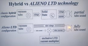
I would disagree with the claim:
This innovative LTD “Loudspeaker Tube Direct” technology allows the use of tubes exclusively for amplification circuitry, with transistors used exclusively for power supply and protection circuits.
Amplification is both current and voltage. Here the voltage is done with tubes and the current with SS amp. That's a hybrid in my books. The SS amp is contributing nearly all of the power. You could be the same thing with much lower power tubes. As an amp its quite stylish through and probably performs to spec.
However in my opinion the sales pitch is misleading giving the impression your buying a true valve amp.
While it is obviously a Hybrid design, it is a definite cut above -most- hybrid designs, where the tube output is just run thru a SS final buffer stage. The Composite Amplifier approach uses the SS part to increase the load impedance to a level the tube(s) can handle directly. As long as the SS part is high impedance, like here, the tube just runs the show. The SS part does need to use high N Fdbk itself to remain transparent while cancelling load current. As long as nothing breaks into oscillation, you have a success story. One does need to be realistic about making "all tube" claims though. I do think Composite Amplifiers are a genius type design, which should get more respect than just "another Hybrid".
There is another Composite Amplifier type design that gets barely mentioned, but is equally fascinating. The Series Composite amplifier. This would (for example ) use a SS power amplifier with conventional voltage output mode. Highly accurate, using N Fdbk for itself. Then a Tube Amp in conventional V output ( but low V and high current, like 0.1 Ohm OT secondary) in series with the SS Amp. The Tube Amp monitors the summed voltage output and makes the final sum V what it wants. You might call it a "Tube Veneer" amplifier. Still sounds like the tube. Then there are two more obscure Composite designs that produce a net current output (series or parallel configuration).
The other "genius" type designs are "tube emulation" 1) Where each output device (which could be a Mosfet too) is constrained (by unusual N Fdbk) to perform as a bigger version of a smaller tube model.
And 2) UnSet where the output device(s) is constrained to operate as a linear triode.
And then .....
a) normal 6HJ5 pentode
b) 6HJ5 with UnSet
c) UnSet and Crazy Drive - ultimate pentode? or CrazyOnSet?
d) just Crazy Drive


.
There is another Composite Amplifier type design that gets barely mentioned, but is equally fascinating. The Series Composite amplifier. This would (for example ) use a SS power amplifier with conventional voltage output mode. Highly accurate, using N Fdbk for itself. Then a Tube Amp in conventional V output ( but low V and high current, like 0.1 Ohm OT secondary) in series with the SS Amp. The Tube Amp monitors the summed voltage output and makes the final sum V what it wants. You might call it a "Tube Veneer" amplifier. Still sounds like the tube. Then there are two more obscure Composite designs that produce a net current output (series or parallel configuration).
The other "genius" type designs are "tube emulation" 1) Where each output device (which could be a Mosfet too) is constrained (by unusual N Fdbk) to perform as a bigger version of a smaller tube model.
And 2) UnSet where the output device(s) is constrained to operate as a linear triode.
And then .....
a) normal 6HJ5 pentode
b) 6HJ5 with UnSet
c) UnSet and Crazy Drive - ultimate pentode? or CrazyOnSet?
d) just Crazy Drive
.
Last edited:
-Which is why you don't want to build an amp and then hook it up to a PSU buildt from whatever money that was left.All amps are modulated power supplies.
- Home
- Amplifiers
- Tubes / Valves
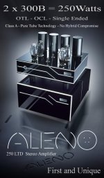
- 250 watts from a SE OTL OCL 300B Amplifier!!!