Put a proper fuse in the IEC drawer and go ahead try it. If you had a dim bulb tester and/or a Variac it would be even safer for initial power tests in general but anyway.

Blue and Brown to mains as you have drawn, no Blue on secondary as the text says. Shield to mains PE (earthground).
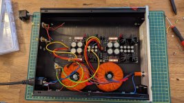
Picture or it didn't happen 🙂Psu boards up and running, 17.6 & 17.59, 17.67 & 17.68v
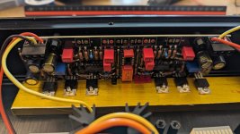
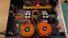
First of all check that the PSUs output polarities are wired correctly to the main board connectors.
Also measure to see if the PSUs output voltages are still good when connected to the main board.
They were fine (v+ to V+ on the main board, V- to V-, gnd to gnd). Did I put VR1 the wrong way around by any chance? Comparing to your build on page 1
All as beforeAlso measure to see if the PSUs output voltages are still good when connected to the main board.
The wiper is in the middle any way you put it so it shouldnt make any differenceDid I put VR1 the wrong way around by any chance? Comparing to your build on page 1
Check if you got one or more LEDs on the main board populated the wrong way around. Cathode is the wider metal inside.
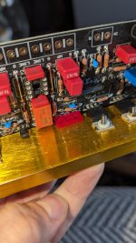
Remove them carefully and reverse them. Don't dwell long with the iron. Help rework with solder wick if you got, they are sensitive. Unless you got some spares. While you are at it inspect both sides for dirt, flux crud, solder bridges, missed joints, dull joints, suspect strength joints, weak pins etc. Canned air, brushes, Kimwipes, Isopropyl Alcohol (IPA) are your friends.

Does it mean I connect the Left barrel pin to one pole of the potentiometer on C, and the right barrel pin to another pin of C on the potentiometer? And then connect the respective right and left inputs to the pre?If yours is a single input only configuration, just continue from RCA barrel pin through signal wiring to pot pin "C" to ground point "G" line-in DCG3 terminal.
*If when touching the volume knob you will get some buzz then run a thin wire from a point C and jam it between the mounting nut for the bracket and the pot.
Yep, from RCA barrel to pot C to line-in G for completing each channel's input signal ground path.
So I tested voltage drop at R10's yesterday - 1.25 and 1.29V
DC offset settled at around 0.
With opamp, output shorted, left channel was showing 0.27V- adjusted to bounce around -0.003 to +0.004
The right channel was at 0.005V
DC offset settled at around 0.
With opamp, output shorted, left channel was showing 0.27V- adjusted to bounce around -0.003 to +0.004
The right channel was at 0.005V
- Home
- Source & Line
- Analog Line Level
- Salas DCG3 preamp (line & headphone)