
All the above answers from 6L6, Tungsten, Mark Johnson, et al. are practical, but some want to go into the diminishing returns area. Naim Audio for exam;le has done alot with power supply improvements for example.
https://www.psaudio.com/blogs/pauls...are-equal-in-importance-to-amplifier-circuits
https://www.psaudio.com/blogs/pauls...are-equal-in-importance-to-amplifier-circuits
I do in fact agree with all of this, and a wise man once said, “The amplifier is nothing but an oscillator for the PSU.” So there’s absolutely merit to it.
In my experience, however, you’ll get more sonic differences and improvements by building another, different, amplifier, than twiddling with the power supply. (This is in no way implying that the VFET is bad in any way… just that different amps sound quite different, but PSUs sound quite similar.)
In my experience, however, you’ll get more sonic differences and improvements by building another, different, amplifier, than twiddling with the power supply. (This is in no way implying that the VFET is bad in any way… just that different amps sound quite different, but PSUs sound quite similar.)
I’ve tried several preamps w the amp, and it has the same signature sound w all of them. Just a bit thin…You can try a different preamp to get a different sound. This would be easy to do. It may be that your preamp is actually the sound that you are hearing.
I tend to share the viewpoint on amps/power supplies. They are gates/valves/oscillators for the power supply.
What goes to the speakers is coming directly from the power supply.
What goes to the speakers is coming directly from the power supply.
Yeah, that was a scary execution with excessive glue over everything.
The articles were more interesting, specifically the importance of maintaining low impedance in the power supply. There are lots of ways of accomplishing this. Capacitance really is the answer. The trick is using the right sizes of capacitors to avoid inductive impedance, so a well executed supply should employ different sizes of caps to maintain a low impedance over a broad frequency range.
The articles were more interesting, specifically the importance of maintaining low impedance in the power supply. There are lots of ways of accomplishing this. Capacitance really is the answer. The trick is using the right sizes of capacitors to avoid inductive impedance, so a well executed supply should employ different sizes of caps to maintain a low impedance over a broad frequency range.
use of super capacitors in the power supplies
last time I looked (eons ago), I didn't found them having any ripple current capacity
maybe that changed, but I wouldn't be surprised calculating that some regular cap is giving better effective results in energy storage
Scourge, Bulwark, Marauder, and Dreadnought.
S and B have Edcor transformers; M and D do not.
S and B have Edcor transformers; M and D do not.
Guess I could try the the different front ends also.
What voltage transformer should I be looking at?
What voltage transformer should I be looking at?
You should be looking at the transformer which is included in the kit-of-all-parts sold by the diyAudio Store.
To find its manufacturer and part number, either check the circuit schematic diagrams designated by the Store (they are attached below) ...
or ...
Check the Detailed Parts Lists linked by the Store. You can answer your own question, two different ways. Have fun!!


_
To find its manufacturer and part number, either check the circuit schematic diagrams designated by the Store (they are attached below) ...
or ...
Check the Detailed Parts Lists linked by the Store. You can answer your own question, two different ways. Have fun!!
_
Last edited by a moderator:
For the audio transformer, @Mark Johnson is 100% correct and his advice is spot on.
😎
The target is a PSU with 36VDC output.
When you rectify AC to DC the DC voltage will be 40% higher than the AC of the transformer. The diodes will steal about 1.5VDC, so for a rough example, a 20VAC transformer -
20 x 1.4 = 28
28 - 1.5 = 26.5VDC
And so forth. Using this you can determine what VAC power transformer you’ll need to build a linear PSU.
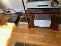
Thought I’d mention this here for what it’s worth. A friend asked me to bring a Class D amp I have to compare to his Naim monoblocks. The speakers are the Wharfedale Linton Heritage 85th Anniversary units.
Out of curiosity I took along my P-channel lottery VFET.
Every so often a match made in heaven occurs between audio components. If you have an opportunity to do so give a listen to the Linton’s and the lottery amp.
Out of curiosity I took along my P-channel lottery VFET.
Every so often a match made in heaven occurs between audio components. If you have an opportunity to do so give a listen to the Linton’s and the lottery amp.
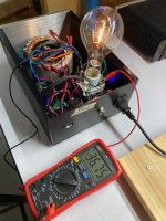
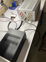
So I went and did this for my P-channel Sony VFET amp today. I adapted a linear power supply I'd made for my ACA by simply swapping out the Antek AS-2218 power transformer I was using for an Antek AS-3428. The latter transformer has a pair of 28V secondaries and another pair of 15V secondaries, unused in this application, on a 300VA core. The 1.3x heuristic predicted 36.4V DC. Since I chose to repurpose a First Watt style single rail PSU with filter capacitors rated for only 35V 😱 I was a little concerned and did some soak testing with a 300W incandescent bulb as load for a while. The voltage drop across the bulb was 36.8V. I watched the capacitors for a half hour or so in the garage without incident until I got itchy to try it with the amp. Note, when I built the linear PSU I went through the trouble of sourcing and using the same style of power connector in the linear PSU that the Meanwell SMPS bricks that were spec'd for this amp use. This is a plug & play replacement for the brick.I’m going to be building a linear power supply for my NPN lottery amp.
With the amp in circuit & playing music I measured 34.8V on the OS boards after the HF hash filter. The bias was 20.5V both channels so I didn't mess with anything. I'm listening to some Jazz Sabbath right now on my main system & it is good. This amp doesn't have the bass or dynamics of an Aleph Jzm or an F5m but I'm imagining there's a bit more of that spooky holographic imaging that VFETs are known for. Cheers.
Attachments
If you have a CRC power supply filter, the voltage at the capacitors connected directly to the bridge rectifier is probably higher than 35V if the voltage at the amplifier board is 34.8V. You can measure the voltage at the capacitors and decide whether they are acceptable.
- Home
- Amplifiers
- Pass Labs
- DIY Sony VFET pt 1