Equal load impedances should give equal outputs.
Hopefully C1 is connected properly, unlike on your schematic.
Check the resistor tolerances, the imbalance difference is around 5%.
Unless you use 1% or better resistors, this amount of imbalance is expected.
Hopefully C1 is connected properly, unlike on your schematic.
Check the resistor tolerances, the imbalance difference is around 5%.
Unless you use 1% or better resistors, this amount of imbalance is expected.
1. Is your filament elevated?
Too much voltage from the cathode to the filament? That causes leakage current from the cathode to the filament. Unbalanced signal.
A filament winding that is center tapped to ground, or that has 100 Ohm resistors from each winding end to ground, is not elevated. Leakage current.
Un-balanced signal.
A filament winding that is center tapped to a +DC voltage, or that has 100 Ohm resistors from each winding to a +DC voltage, is elevated.
Little or no leakage current. Balanced signal.
2. A 5% plate load resistor that is 2.5% High, and the other 5% plate load resistor that is 2.5% Low, will cause a 5% signal difference, push versus pull.
3. A gassy 12AU7 will have grid current (current that un-balances the circuit).
Pretty sure it's just resistor tolerances.
Dynaco used carbon comp 1W resistors for the splitter in their power amps,
but they hand matched those critical resistors..
Dynaco used carbon comp 1W resistors for the splitter in their power amps,
but they hand matched those critical resistors..
I'm very sorry, I should have made it clear that it is a simulated circuit, so the components are perfect, zero tolerance deviation. There is still imbalance and I was curious to find the reason and learn. In a real circuit, of course, c1 will be connected.
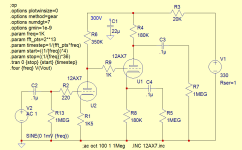
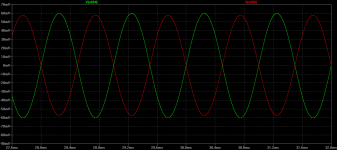
It may be that the sim has the tube characteristics with the output impedance of the cathode different from that of the plate output impedance. Try a different tube in the sim like a 12AU7 and see if it shows a different balance. This is a known issue with cathodyne inverter.The circuit show near 2V difference between outputs, why?

As long as the load on the plate is the same as the load on the cathode, the outputs will be the same.
After all, the cathode current is the same as the plate current, and V = I x R.
After all, the cathode current is the same as the plate current, and V = I x R.
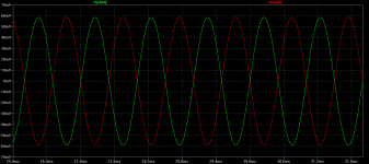
It's not a sim error. Not connecting C1 causes ripple on the B+. The anode output of the cathodyne has low PSRR so the ripple is added to the signal. The cathode output has high PSRR so doesn't see the ripple. If you connect C1 in the sim the outputs are the same as they should be.
Yes, if you actually do not have C1 connected for the sim, that will cause an error due to unwanted effects from R3,
which among other things, makes the plate resistor larger, and hence the plate output voltage larger.
Even if it is connected, the test frequency must be high enough so the impedance of C1 is very low to ground,
in order to avoid this effect.
which among other things, makes the plate resistor larger, and hence the plate output voltage larger.
Even if it is connected, the test frequency must be high enough so the impedance of C1 is very low to ground,
in order to avoid this effect.
Recalling an article interview with David Hafler and this issue in one of the amps, his explanation for a circuit adjustment was that the unbypassed cathode load resistor created degenerative FB that created the signal gain differential at the cathode. If memory serves correctly. Searching for the mag. it's in.
The plate and cathode signal currents are the same, so equal loading gives equal outputs.
Sure the output impedances at the plate and cathode are different, but that doesn't matter with equal loads.
However, if there is significant capacitive loading, the unequal Routs will cause an imbalance at very high frequencies.
Perhaps Hafler was discussing why the cathodyne does not have the imbalance problem of the "cathode-coupled phase inverter",
which does have an inherent output imbalance, due to the finite impedance of the CCS (or resistor) to ground.
With a perfect (infinite impedance) CCS, it too would have perfect balance. Of course, the correct fix is to drive it balanced.
Then it would have perfect output balance, by virtue of the symmetry.
Many thanks to all, so I'll connect C1 and try another tube model as well in order to see what happens.
The most mid-band gain you can get in practice with two 12AX7s will be around 40dB, but it will usually be less.
Especially with the plate resistors at only 100k.
Especially with the plate resistors at only 100k.
If it isn't the disconnected C1, it could be grid current of U1. Maybe it's working in class A2 instead of A1.
Cathodyne:
1. The Main current is from the cathode to the plate. Ic = Ip
Matched cathode and plate resistors gives exactly the same signal voltage amplitude (discounting extremely high frequencies, where capacitive current is a factor.
At most audio frequencies, all is well.
2. Any form of grid current Robs current from the Main current path. In that case Ic is not equal to Ip.
The signal voltage amplitudes are not matched. Not good.
3. Any form of cathode to filament Leakage current (DC or Signal), Robs current from the Main current path. In that case Ic is not equal to Ip.
The signal voltage amplitudes are not matched. Not good.
Some simulation programs work well for case 1. above.
Many do not work well for cases 2. and 3. above, they do not have the factors in the program.
There, I said it.
Of course leaving C1 disconnected was the real cause of your problem.
But do not overlook the potential problems of 2. and 3. in a real circuit.
Last edited:
Some old designs put a VR at R8, a brute force solution for this kind of issues in a real circuit. But then You get the paranoia of constantly controlling if the simmetry mantain as the valve ages.. not nice.
Stupid of me! ... Now the outputs are perfectly equal.
Another day, another lesson...
Thank you very much to all.
You shouldn't be very concerned about a bit of unbalanced output. If you are running a PP amp in class A, the two different signals are summed in the transformer 100% of the time so you get the equivalent of power out that is slightly under the 2x the highest half. Example, 8 + 7.9 = 15.9 .... It's the same in class AB operation as there is no time when there is not at least 1 of the tubes that is conducting, and for most of the time of the cycle both do unless you are very deep into the AB biasing. Unless you have a very large imbalance, there would be no time when both tubes are in cutoff at the same time. If you don't like the idea of a tube crossing into the cutoff zone, don't run an amp biased for AB operation. In the end it takes a very large deviation from balanced operation to have any audible affect and that would be a serious component issue to be addressed. You would notice it as a channel to channel power imbalance. So according to the theory that if both load resistors are equal, then there has to be balance, it matters not if the tube ages until its own operation is compromised enough to start clipping early at high volume levels.
Concertina stages with equal plate load resistors and equal grid resistors, Rg, are balanced even with old aged tubes . . .
As long as the tube is Not Gassy; and as long as the filament to cathode leakage has Not degraded with age.
Caution: Some brand new tubes can have gas, and some brand new tubes can have filament to cathode leakage.
The Quality of Your Parts May Vary (QYPMV)
As long as the tube is Not Gassy; and as long as the filament to cathode leakage has Not degraded with age.
Caution: Some brand new tubes can have gas, and some brand new tubes can have filament to cathode leakage.
The Quality of Your Parts May Vary (QYPMV)
- Home
- Amplifiers
- Tubes / Valves
- DC Cathodyne not balanced