
Odyssey pad has excellent thermal conductivity of 12.8W/mK but is WAY too thick to be effective here. Aluminum heatsink is about 160-200W/mK, and copper is 400w/mK.
And you've already taken a hit on thermal performance with the TO-247, which has only 1/3 the surface area in contact with the heatsink as TO-3.
And you've already taken a hit on thermal performance with the TO-247, which has only 1/3 the surface area in contact with the heatsink as TO-3.
Be interesting to test though. If it doesn't work I'll make up some aluminium or copper spacers
How about leaving the heatsink in the original orientation and mounting the TO-247's in TO-3 sockets the usual way?

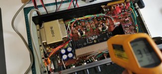
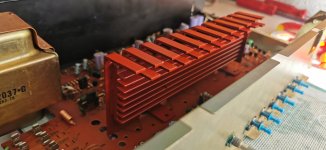
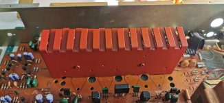
@Phloodpants I have done one already as you suggested, I just wanted to try them vertical this time to see how it looks
ok so here we are
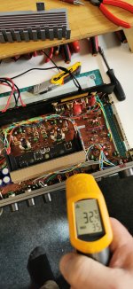
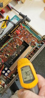
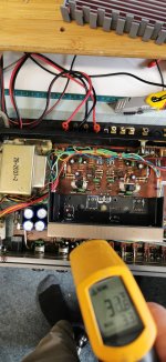
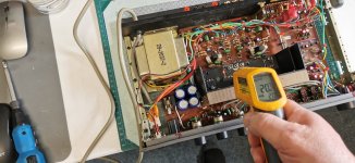
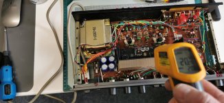
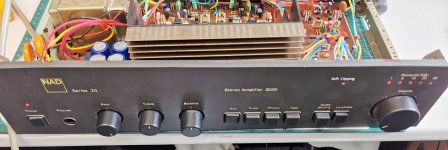
@Mooly i used the amp we converted with the soft clip light and TIP35 transistors
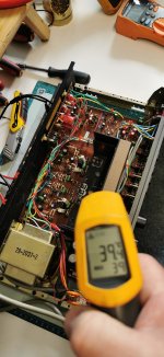
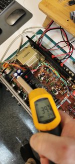
as you can see therte is very little difference,so the pads must work
appologies for the sock veiw and a bit blurred but i had to hold camera and infra thermal at the same time
@Mooly i used the amp we converted with the soft clip light and TIP35 transistors
as you can see therte is very little difference,so the pads must work
appologies for the sock veiw and a bit blurred but i had to hold camera and infra thermal at the same time
Attachments
-
 25% vol thermal pad.jpg484.4 KB · Views: 178
 -
 25% vol silica 3.jpg464.8 KB · Views: 170
 -
 25% vol silica 2.jpg428.2 KB · Views: 161
 -
 25% vol silica 1.jpg468.6 KB · Views: 149
 -
 idle thermal pad 10 mins.jpg438.5 KB · Views: 151
 -
 idle silica pad 10 mins.jpg438.8 KB · Views: 155
 -
 idle silica 3 10 mins.jpg480.9 KB · Views: 154
 -
 idle silica 2 10 mins.jpg477.3 KB · Views: 148
 -
 ambient thermal pad.jpg429.3 KB · Views: 149
 -
 ambient standard silica.jpg448.7 KB · Views: 140
 -
 IMG_20240416_150513.jpg290 KB · Views: 156
Wouldn’t it just be easier/better to form the leads such that you don’t need a spacer?Be interesting to test though. If it doesn't work I'll make up some aluminium or copper spacers
What's being compared here? Two kinds of sil-pads and mica? Are the 3mm thick pads involved here somehow?
5C on top of the transistor is actually a pretty big difference and that gulf will widen with more power applied.
5C on top of the transistor is actually a pretty big difference and that gulf will widen with more power applied.
I don't want to throw a spanner in works over these pads but my worry was not so much the temperature everything gets to after its been on a while but rather what happens under dynamic conditions.
For example... bolt a power transistor to a suitable heatsink as a test and bias it for say 5 seconds at 50 watt dissipation and then back to zero. I know from experience how fast that rise in temperature can be. If it were not on a heatsink it would go from cold to sizzle water to leads unsoldering themself in a 2 or 3 seconds. How would the pads cope with that is my genuine worry.
For example... bolt a power transistor to a suitable heatsink as a test and bias it for say 5 seconds at 50 watt dissipation and then back to zero. I know from experience how fast that rise in temperature can be. If it were not on a heatsink it would go from cold to sizzle water to leads unsoldering themself in a 2 or 3 seconds. How would the pads cope with that is my genuine worry.
I guess then it will be the materials ability to distribute a sudden rise, rather than a gradual one. I think if a transistor was subject to a rise that quick the heat sink would be pretty irrelevent wouldn't it?
The heatsink would absorb much of the heat provided that the thermal interface was good.
You can test how good it is with any old power transistor and a power supply and heatsink. Set a voltage in the 20 to 30 volt region from a current limited bench supply (set the limit to say 1 amp) and choose a resistor to give about 1 amp current when connected. The transistor will heat up super rapidly.

You can test how good it is with any old power transistor and a power supply and heatsink. Set a voltage in the 20 to 30 volt region from a current limited bench supply (set the limit to say 1 amp) and choose a resistor to give about 1 amp current when connected. The transistor will heat up super rapidly.
Providing conditions stay stable heat shouldn't be an issue but I guess the proof is fitting then testing them
Try at https://www.chk-electronics.com/RA-2210G.html and https://www.cliffuk.co.uk/products/phono/index.htm.
Poundy have maybe a better source .
Poundy have maybe a better source .
I make them up mainly from scratch. The terminals are quite readily available, but the bases I make out of perspex and shamfor the edges
Most of my gear I get from@poundy I see you have done a few of these and replaced the phono sockets, where did you source these?
https://www.soundimports.eu/en/
https://www.soundimports.eu/en/091-1140.html
👍
- Home
- Amplifiers
- Solid State
- Last, but (hopefully) best ever modified and complete NAD 3020