Thank you 🙏 , hopefully for us that don’t use HQ player they can come up with a solution for the pcm2dsd module tooThe original circuit is from my AK4493 dac which I also use for measurements so it has much higher cutoff than the dual OPA1632 filter stage in this test. The latter also has a steeper filter. So for RTZ dac it is better to use the dual OPA1632 stage in this test.
A second note:
Also Pavel (ppy) had found the 'AMSDM7' type of modulator giving the best noise floor while looking at his DSC1/2 design..
Also Pavel (ppy) had found the 'AMSDM7' type of modulator giving the best noise floor while looking at his DSC1/2 design..
Last edited:
2. ThorstenL's suggestion (based on Birt)
This output stage is based on what ThorstenL simulated in post #2150 although without the passive input filter.
Here is the schematic.
View attachment 1288879
Two notes, first, naturally the second stage should also have used "Birt" and a common mode + diff mode MFB filter.
Not sure how much difference this would make to the outcome though.
If the second stage distortion hypothesis is correct, then a "Birt" in the second stage would show improvements,
Also, I probably would not suggest OPAx210. OPA2156 would likely have been my choice (over OPA1656). Note, I also have no issues with OPA1632, except that it is a single vendor part, with very little alternatives.
Thor
A couple of comments from my side regarding the low-level distortion:
1. The first quasi-multibit modulator bohrok2610 tried was the one from post #763 of this thread, https://www.diyaudio.com/community/threads/return-to-zero-shift-register-firdac.379406/post-7403058 , which is a software implementation of my PWM8 modulator (see https://linearaudio.net/sites/linearaudio.net/files/03 Didden LA V13 mvdg.pdf for an explanation). It made the distortion products at -60 dBFS drop drastically, in fact they became invisible. Due to equipment limitations, the test had to be done at a DSD128 rate rather than the intended DSD512. I mention it because this is the only modulator of which the exact algorithm isn't secret.
2. I suspect that solving the offset issue in the PCMtoDSD, if there is one, won't solve the distortion, but will make the closely spaced peaks coincide in frequency.
3. I will explain my hypothesis later, but if it is correct, then more passive filtering (as recommended by ThorstenL, albeit based on a misconception about how the DAC works) or the use of op-amps with a greater ratio of the slew rate to the gain-bandwidth product (such as FET op-amps) in the first filter stage might help.
4. The measurements were done with a resynchronized bit clock, not with a (divided) master clock. I mention this because it could be worse with a (divided) master clock at a multiple of the bit clock frequency.
Last edited:
Regarding the hypothesis:
You can regard an ordinary single-bit sigma-delta modulator as a kind of time-quantized frequency modulator: the average frequency of the ones coming out of the sigma-delta modulator is fs/2 plus something that is proportional to the input signal. As the modulator's output signal is a discrete-time signal, the locations where ones can occur is defined by the clock, hence that "time-quantized".
At 0 dB DSD, the momentary frequency of the ones is modulated all the way from fs/4 to 3fs/4, at -60 dB DSD, from 0.49975 fs to 0.50025 fs. That is, the FM carrier frequency is fs/2 and the peak frequency deviation is 0.00025 fs, which is 1411.2 Hz at DSD128 and 2822.4 Hz at DSD256 (which is the rate bohrok2610 used for most of his measurements). With a 1 kHz audio frequency, the frequency deviation is larger than the audio frequency, which means that there will be several sideband peaks around fs/2.
If those peaks intermodulate with each other, they can produce distortion products in the audio band. If there is a small DC offset somewhere (like you can get in digital when you truncate a 32 bit number to 24 bit, for example) that will shift the carrier and the FM sideband peaks slightly in frequency. Because the modulator is a discrete-time circuit, there will be aliases that shift in the opposite direction. Intermodulation with the aliases might then produce the slightly frequency-shifted audio signal peaks, although I haven't quite figured out what peak intermodulates with what yet. An experiment where a small offset was deliberately subtracted from the digital audio signal shifted the positions of the audio tones (of the tones that were between 2995 Hz and 3005 Hz anyway).
Properly dithered quasi-multibit modulators should not produce an FM-like spectrum, but just shaped noise. When there are no out-of-band tones, they also can't intermodulate to produce distortion products in the audio band. That would explain why bohrok2610 didn't see the distortion with my PWM8 algorithm, nor with HQPlayer's AMSDM7 modulator (not to be confused with ASDM7).
The question is where the intermodulation between the out-of-band tones takes place.
If it is plain old intermodulation between out-of-band signals in the output filter, more passive filtering before the first op-amps should help, as should using op-amps with a larger input stage "linear" range. For example, FET op-amps with a large ratio of their slew rate to their gain-bandwidth product. (As tones around half the sample rate often cause trouble in systems based on single-bit sigma-delta modulation, I already took two measures to reduce their effect: the notch at half the sample rate of the FIRDAC and the 8.2 nF capacitors to ground straight at the DAC outputs. Apparently what bohrok2610 sees now is what is left despite these measures.)
It could also be intermodulation due to disturbances on the reference supply or the clock, for example crosstalk from the data signal to the reference or clock. However, bohrok2610 did many experiments with different reference supply decoupling and even with a different reference regulator and saw no difference in the low-level distortion, while he did see an effect of his different output filters (as shown in his series of posts with measured spectra).
Last edited:

" using op-amps with a larger input stage "linear" range. For example, FET op-amps with a large ratio of their slew rate to their gain-bandwidth product."
OPA828.. I am using it together with OPA1656 in the last years. Though Thorsten can be right, OPA2156 looks better then 1656 in this regard.
OPA828.. I am using it together with OPA1656 in the last years. Though Thorsten can be right, OPA2156 looks better then 1656 in this regard.
Last edited:
The question is where the intermodulation between the out-of-band tones takes place.
A THEORY from me (not certainty). The OPAx210 internally is "rail to rail", or common emitter output:
Current sourcing and sinking is limited and quiescent current is VERY low. In the circuit we have switching related artifacts at ~12MHz (or 24MHz) and a feedback loop that is in effect a 2.2nF Capacitor.
This means rf rides through to the output stage. What does it do there is to get to the base of the output transistor, which is in effect also the VAS stage.
Now OPA1632 has buffered outputs, likely Diamond Buffer type and likely with significant quiescent current:
This output stage would "sink" RF noise even in "open loop" condition, it will not enter the circuit inside the IC in a similar manner.
2. ThorstenL's suggestion (based on Birt)
This output stage is based on what ThorstenL simulated in post #2150 although without the passive input filter.
Here is the schematic.
Just to note, my "real" suggestion would look like this:
Probably with LT1028/1115 instead of OPA1611/12, though OPA(2)828 or OPA1656/2156 would also be options.
The THS6012 is resymbolised as TPA6120, use either one, OR ANY OTHER CFB Op-Amp with diamond or other emitter follower outputs. Note the CFB output stage has gain, that is needed to both offset the loss of loop gain of the main OPA and to avoid exceeding the CM Range of THS6012, which causes it to go into polarity inversion.
Servo Op-Amp is not that critical, but at OPA1678 should be used.
Thor
Last edited:
How do you estimate the OPA2210 output stage quiescent current? It must be less than 2.2 mA because the whole op-amp typically draws 2.2 mA, otherwise I don't see anything indicating the value.
If there were a big Miller compensation around the output stage, I would estimate that the quiescent current is about 400 uA because of the 35 ohm high-frequency open-loop output impedance. The compensation scheme is, however, more complicated than that.
Anyway, if your hypothesis is correct, a few pull-down resistors drawing a few milliamperes out of the op-amps of the first filter stage could help. It would reduce the voltage swing on (and hence the distortion of) the input stage as well as the distortion of the output stage.
How do you estimate the OPA2210 output stage quiescent current? It must be less than 2.2 mA because the whole op-amp typically draws 2.2 mA, otherwise I don't see anything indicating the value.
I estimate it as "low". The entire OPA has 2.2 mA, the input stage at least a few 100uA to get so low noise. Probably closer to 1mA for input. So likely less than 1mA in the output stage.
Anyway, if your hypothesis is correct, a few pull-down resistors drawing a few milliamperes out of the op-amps of the first filter stage could help. It would reduce the voltage swing on (and hence the distortion of) the input stage as well as the distortion of the output stage.
Given the outputs are pulled to 0V, 2.5V @ 375R+ 845R already draws ~2mA.
Thor
Good point, I forgot about that. It's actually 1.24 V and about 1 mA: half the outputs are at zero because of the RTZ functionality, the other have data on them, so on average one out of four is high.
It would make more sense to try a pull-up rather than a pull-down resistor then.
It would make more sense to try a pull-up rather than a pull-down resistor then.
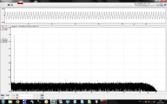
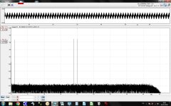
Hi ... since I can see that you are talking about the filter stages and distortion at higher frequencies I thought this might be relevant to your talk ....
The attached FFTs are when using Marcel's output stage - without - the common mode circuitry and with a slightly different PCB layout. Also, I use the OPA1656 in the last stage whereas the first stage still is the OPA2210. There are also some different decoupling capacitors around the opamps but basically the same structure.
Cutoff frequency has been re-calculated to be 65 kHz for the first stage (thanks Marcel for the MFB document earlier in this thread & the Okawa-denshi online calculator 😉 ) whereas the second stage is as Marcel designed it (I just realized that I have forgotten to change the second stage's cutoff frequency so it is still at, to my memory, 80 kHz?).
The sound files I used were generated with WaveGene - a software freely available (although aged some years by now). At -1 dB for the 1 kHz file (384 kHz 32 bit PCM) and at -12 dB, -9 dB and -9 dB for 1kHz, 19kHz & 20kHz, respectively, for the "IMD" file.
Playback through HQPlayer at DSD128 with ASDM7ECv2 modulator (just the one I happen to use for comparability without challenging my computer beyond its capabilities). Output level - 1dB in HQPlayer for both files.
Cosmos ADC (4.5V RMS sensitivity), Fs 96 kHz, 132k samples, Blackman-Harris 7 point window. WaveSpectra FFT software (also freely available, to my knowledge the same developer). Above 48 kHz there are not any other distortion pins except the increased DSD noise level.
The DSD DAC was not Marcel's (I can't get my version to perform optimally, unfortunately) but an experimental discrete DSD DAC (which I at least currently am not at liberty to share more details about).
My reason for posting this is that as far as I can see the output stage (w. OPA1656) in this context does not perform "worse" at high frequencies ... ? Just my input in case it may be helpful to your talks about the filter stages.
Cheers, Jesper
Attachments
As I mentioned in post #2180 I have already tried OPA1612 instead of OPA2210 in "stock" filter. It did not improve distortions at 10k. It seems to have same internal structure as OPAx210 but slightly higher quiescent current (3.6mA).
My conclusions of my tests are that passive filtering before first op amp stage is important and OPA1678 is probably not the best op amp for second stage. But I will stick with OPA1632. It is quite cheap and has diy-friendly packages. Also slightly improved version (OPA1633) is now available although IME no difference to OPA1632 in practice.
My conclusions of my tests are that passive filtering before first op amp stage is important and OPA1678 is probably not the best op amp for second stage. But I will stick with OPA1632. It is quite cheap and has diy-friendly packages. Also slightly improved version (OPA1633) is now available although IME no difference to OPA1632 in practice.
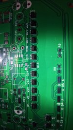
Diy'd some wire snippet desoldering pincers, greased them up with some solder, and off the disoriented BCM56DS came. Took less than a second per part.
I don't know if it's more embarrassing or not, but I saw the dot on the part, but missed the marking on the silkscreen. After comparing the schematic and the pinout, I misidentified the emitter of Q28A and didn't care to check again until after they were soldered, which was when I noticed that there are indeed orientation markings on the silkscreen...
Either way, onwards and forwards.
Attachments

Would be interesting when someone with a transformer solution could do the same measurements as Bohrok did.
When he also sees elevated distortion around 10Khz, it would mean that the filter op-amps are only playing a minor role.
Hans
When he also sees elevated distortion around 10Khz, it would mean that the filter op-amps are only playing a minor role.
Hans
Possibly I will built a slightly modified Marcel dac and try output transformers with it. If that happens, probably the particular transformers would be expensive and or unavailable as standalone components. Also, not sure how much could be said regarding specific details until perhaps some later time. For now, experience with Andrea's discrete SE output stage combined with some 1:1 prototype line level transformers can be pretty good according to my admittedly finicky tastes. We will have to see over the coming months what additional information will be released.
Hi again ... I think I'll just add a bit more information to clarify this comment of mine:
It is not so that I can't make it work as such - it works fine, also with the modifications I posted a schematic for earlier in the thread - it is only that I, at least until now, cannot make it perform at the level that bohrok2610 did. I have made three versions with different layouts for the clock & LV574s and they all quite consistently perform at -112 to -113 dB THD (with slight variations in the harmonics' level). DSD128 & DSD64.
I have also tried the 74AC574 and it actually performs a little worse than the 74LV574.
Cheers, Jesper
The DSD DAC was not Marcel's (I can't get my version to perform optimally, unfortunately)
It is not so that I can't make it work as such - it works fine, also with the modifications I posted a schematic for earlier in the thread - it is only that I, at least until now, cannot make it perform at the level that bohrok2610 did. I have made three versions with different layouts for the clock & LV574s and they all quite consistently perform at -112 to -113 dB THD (with slight variations in the harmonics' level). DSD128 & DSD64.
I have also tried the 74AC574 and it actually performs a little worse than the 74LV574.
Cheers, Jesper
- Home
- Source & Line
- Digital Line Level
- Return-to-zero shift register FIRDAC