Check wiring, each and every part with one leg out of circuit for its value, pcb traces, solder joints and drive unit.
You need an LCR meter (handheld or a pc with sound card) or a multimeter with a circuit jig for it.
You need an LCR meter (handheld or a pc with sound card) or a multimeter with a circuit jig for it.
Can anyone help?
Well, Barry, I'm no system7, but I can see a burnt out resistor and a corroded inductor lead on the faulty board, both of which require attention.
All bipolar electrolytic capacitors, the four black ELCAP and the single blue ALCAP, will require to be replaced (both speakers).
The one coil that's purple? I didn't get it..
Instead of using clear insulating varnish on the copper wire, purple varnish has been used on that one. It makes no sonic difference!
Check wiring, each and every part with one leg out of circuit for its value, pcb traces, solder joints and drive unit.
You need an LCR meter (handheld or a pc with sound card) or a multimeter with a circuit jig for it.
Both the boards are covered with glue and will be messy. Is there a way to re-do everything a new? Can I use/remove what's good and remount the whole lot. I understand the originality and keep how the designer intended but they had limits, budget. The terminals can be of better quality, internal wiring and crossover usage of more ifficient materials. Same goes with the 770's. Just get the music to the drivers as pure as I can.Well, Barry, I'm no system7, but I can see a burnt out resistor and a corroded inductor lead on the faulty board, both of which require attention.
All bipolar electrolytic capacitors, the four black ELCAP and the single blue ALCAP, will require to be replaced (both speakers).

Both the boards are covered with glue and will be messy.
A competent DIY guy should be able to deal with that. The old, hardened glue may be brittle and just chip off using a pocket knife.
P.S. I've read elsewhere that the 4R7 resistor is known to run hot and burn the board.
I would replace it with a higher wattage rating and mount it proud of the board to allow air cooling.
Last edited:
The glue is that type from glue guns like plastic/rubber. I will have to heat then scrape off and its everywhere. You have seen the new pics right? Don't want to cause more damage. "AARRR I DON'T KNOW WHAT TO DO"I would not change the internal wiring. Only redo maybe corroded connections or solder them.
You make less faults keeping original pcb and just change the capacitors.
Im gonna clear my mind from all this for a bit then with fresh head do what I gotta do. Thanks guys
Before you start designing a new board, have all the passive parts measured and traced to original
schematic. It is not that difficult. Take your time.
schematic. It is not that difficult. Take your time.
...have all the passive parts measured and traced to original schematic.
Unfortunately, the crossover schematic for the vintage Mission 720 is elusive.
The boards are original.
So, you meant traced to original 'board' rather than traced to original 'schematic'?
So, you meant traced to original 'board' rather than traced to original 'schematic'?
I am confused by all these speakers. We have two way Mission 770, 737R and now a very broken 720 three way..
I have located a sort of schematic for the 720:

Something to go on here:
https://www.diyaudio.com/community/threads/mission-720-refurb.299278/
What is the plan here? The 720 looks difficult.
Best regards, Steve.
I have located a sort of schematic for the 720:
Something to go on here:
https://www.diyaudio.com/community/threads/mission-720-refurb.299278/
What is the plan here? The 720 looks difficult.
Best regards, Steve.
Thanks system7, plan is to recap the crossover board on 720 so the midrange will work. One board is free to handle but still covered in glue. The other is still glued down inside the speaker. Both the crossover boards need to be cleared from the glue so "I" or someone can re-cap them. The glue is horrible and if during cleaning them no extra damage is done to the tracks its ok, if the tracks become damaged the crossover's will have to be made from scratch! That's all.
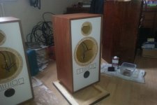
The 720's are beautiful so for naw I will put them to one side. I will take pics of them and show everyone.
770's tweeters will be cleaned and new ferrofluid replaced. Once done mission 770 speakers will be placed on stsnds playing sweet music. During the course of getting this done the 720's became available and threw in a curve ball. Bonus really, a nice rare set of speakers.
As long as the soldering on the bottom looks good you can replace caps and resistors by cutting the old ones out leaving their wires standing up and solder there.
Can be a good solution if someone only has a low wattage soldering iron at hand.
But more orthodox it would be to make new and not fix the board quick and dirty with glue again. Mission did not create a good serviceable part by using glue
Can be a good solution if someone only has a low wattage soldering iron at hand.
But more orthodox it would be to make new and not fix the board quick and dirty with glue again. Mission did not create a good serviceable part by using glue
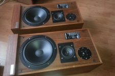
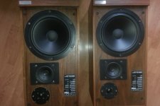
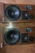
These are them the Mission 720. Nice aren't they? All that has to be done is re-cap the crossover's. Worth saving in my opinion, first range of Mission speakers dated from I think late 1970's.
Attachments

For now I've tidied up listing room and gonna chill with my Pro9's and 1960's Pioneer Er420 valve receiver. Time for some Pink Floyd and others to mellow out.
Thanks everyone for your input and interest.
Thanks everyone for your input and interest.
When you do get round to replacing the Mission 720 capacitors, Barry, check out Willys Hifi.
https://willys-hifi.com/collections/electrolytic-capacitors-non-polarised
Looking at system7's image in post #73, we can see a parallel combination of 25 uF and 16 uF, which adds to 41 uF.
Be prepared to make similar parallel combinations to approximate the values printed on those old, black ELCAP capacitors.
Here's an example shopping list (for one crossover board):
41 uF = 2 x 22 uF (to be connected in parallel)
60 uF = 1 x 56 uF + 1 x 3.9 uF (to be connected in parallel)
10 uF = 1 x 10 uF
16 uF = 1 x 16 uF
6 uF = 1 x 6 uF
All the above values are available at Willys Hifi as Mundorf ECap capacitors which are "ideal for vintage loudspeakers".
- Home
- Loudspeakers
- Multi-Way
- FINALLY, getting Mission 737R just for the woofers, why?