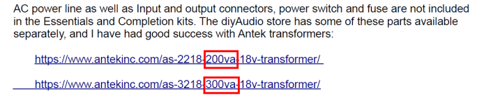
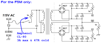
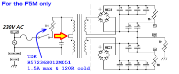
I'm not building an F5m right now, but if I were, I'd choose the CL-80 inrush current limiter for 115VAC transformer primaries. I'd choose the B57236S0121M051 inrush current limiter for 230VAC transformer primaries. Both ICL choices assume the F5m uses a 200VA or 300VA transformer as Nelson Pass specified in his write-up.
DigiKey link 1
DigiKey link 2
No doubt other DIYers will make other choices.
_
DigiKey link 1
DigiKey link 2
No doubt other DIYers will make other choices.
_
Attachments

Depending on whether you are willing to wait for the restock of the essentials kit, there are alternate paths. A pair of standard F5 boards from the store cost $25 and may be adapted to the F5m circuit. The input JFet pairs may also be purchased separately from the store.
The completion kit will be a good start to get your build going. The question is what to do about the output FETs.
The completion kit will be a good start to get your build going. The question is what to do about the output FETs.
tonyEE:
I was first in yet could not get order to checkout. Could only get a shopping page. Took over 30 minutes got the last of it. From the hospital. Now dealing w/phone as conputer certs crashed. Typing on phone impossibe, I quit.
I was first in yet could not get order to checkout. Could only get a shopping page. Took over 30 minutes got the last of it. From the hospital. Now dealing w/phone as conputer certs crashed. Typing on phone impossibe, I quit.
For those using the PSU board and parts included in the kit ... and considering some hot-rodding of their own... Nelson has this to say (quote from article);
"The power supply thermistors are rated at 5 amps, which theoretically allows about 2.5 amps per channel bias current. Realistically, above about 1 amp bias per channel you will want to consider thermistors of about 5 ohm resistance such as the Epcos B57236S0479M000."
The article shows recommended bias currents of between 1A1 and 1A4 per channel based on estimated 30C temp rise above ambient for various heatsinks.
For those that wish to push the envelope and also want to try to find their own substitute parts and/or use bigger heatsinks with even higher bias currents and/or rails, it's worth noting that the thermistors on the boards also serve as part of the filter network. So, tempco and initial resitance along with current rating may factor into the decision of which part to use in that place.
Note - these are the three thermistors on the PSU board, not the additional thermistor previously discussed in series with the transformer primary.
tl;dr - Have fun!
Edited to add - I didn't do any of the calculations myself... and I barely understand the fundamentals, but I think I got the gist of what Nelson was recommending and why. 🙂
"The power supply thermistors are rated at 5 amps, which theoretically allows about 2.5 amps per channel bias current. Realistically, above about 1 amp bias per channel you will want to consider thermistors of about 5 ohm resistance such as the Epcos B57236S0479M000."
The article shows recommended bias currents of between 1A1 and 1A4 per channel based on estimated 30C temp rise above ambient for various heatsinks.
For those that wish to push the envelope and also want to try to find their own substitute parts and/or use bigger heatsinks with even higher bias currents and/or rails, it's worth noting that the thermistors on the boards also serve as part of the filter network. So, tempco and initial resitance along with current rating may factor into the decision of which part to use in that place.
Note - these are the three thermistors on the PSU board, not the additional thermistor previously discussed in series with the transformer primary.
tl;dr - Have fun!
I suppose that depends on what parts you want to use. Available and cheap are relative. The 9140s provided with the kit are obsolete and were kindly provided by Nelson for a good reason vs. more typical parts carrying the same part number made by different manufacturers (previously explained).Aren't they available and cheap?
Edited to add - I didn't do any of the calculations myself... and I barely understand the fundamentals, but I think I got the gist of what Nelson was recommending and why. 🙂
To be a cool guy you want the Harris part for Q3, and you're not getting that at Mouser or Digikey.What is the output question? Aren't they available and cheap?
Attachments

Oh yes. The Harris thing.
Without opening that whole thing again too far, are the Vishay/Siliconix devices the same as IR/Infineon? DigiKey has both.
Without opening that whole thing again too far, are the Vishay/Siliconix devices the same as IR/Infineon? DigiKey has both.
Last edited:
Hi Mark, I ran the numbers and the 200 VA seems to be OK, i.e. enough power and some margin assuming an 8 ohm load. Does this make sense to you or do I need the 300VA transformer? Nelson listed the 200VA and the 300 as options but I wonder if the 200 is OK. I ask because I have a few 200's as well as a 400 on the way. Thanks in advance for any enlightenment, Oh yeah. My questions assumes using the higher 1.4A bias.I'm not building an F5m right now, but if I were, I'd choose the CL-80 inrush current limiter for 115VAC transformer primaries. I'd choose the B57236S0121M051 inrush current limiter for 230VAC transformer primaries. Both ICL choices assume the F5m uses a 200VA or 300VA transformer as Nelson Pass specified in his write-up.
DigiKey link 1
DigiKey link 2
No doubt other DIYers will make other choices.
_
Last edited:
Dang, got down in this rabbit hole again. It looks to me like Vishay/Siliconix parts are Harris or closely derived. Harris --> Intersil --> Vishay.
IR --> Infineon.
No?
IR --> Infineon.
No?
The choice of transformer power rating will depend on the preferred bias current. To support 1.4A bias with a single transformer, 300VA is best. This is a conservative rating that will ensure that the secondary voltage (either 18Vac or 20Vac) is delivered under load.
A 250VA transformer is also an option with 18Vac secondaries. Triad Magnetics is a good brand to look for.
A 250VA transformer is also an option with 18Vac secondaries. Triad Magnetics is a good brand to look for.
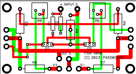
It's a fun little exercise, consider it a ten minute "brain teaser". These two puny hints may accelerate your solution:
attachment below
- In that graphics file, wherever the red copper layer and the green copper layer overlap (see yellow circle), only red is displayed. There is no visual indication that green is present -- even though you know it is.
- Nelson Pass's F5m circuit schematic shows the intended connections between R2 and the other components. It's a very safe assumption that Nelson laid out the PCB correctly and the layout matches the schematic.
attachment below
Attachments

R2 connects between GND and IN (+). I am just guessing that the green line coming out of it connects to G (the line with R5 on it) but it is hidden under the red line. I assume that you would have to be able to see both sides of the board to know.
Oh, little doubt there! Okay, light dawns on Marblehead!Nelson Pass's F5m circuit schematic shows the intended connections between R2 and the other components. It's a very safe assumption that Nelson laid out the PCB correctly and the layout matches the schematic.
OK. I'll use the 400VA. It's a sunk cost so no need to buy smaller.The choice of transformer power rating will depend on the preferred bias current. To support 1.4A bias with a single transformer, 300VA is best. This is a conservative rating that will ensure that the secondary voltage (either 18Vac or 20Vac) is delivered under load.
A 250VA transformer is also an option with 18Vac secondaries. Triad Magnetics is a good brand to look for.
I too ordered a 400VA since Antek was out of stock on the 300VA. How does that change the bias? And from a long term perspective, is it worth getting the 300VA once available? Will that change the quality of sound?
@TomR. I suppose you can turn the bias up higher if your heat sink can handle it.. Papa sez distortion decreases wth bias increase. But... lookng at the curves at 1A bias in the initial document, the distortion looks pretty good as it is. 1.4A should be an improvement. But is more needed? My guess is no but then again, playing around with these things is what DIY is about.
with 400 instead of 300 firecrackers, you're erring in direction of better
not exactly the same, but better to have more gallons in reservoir than less
not exactly the same, but better to have more gallons in reservoir than less
Am I the only one going for the 2U chassis and 200VA transformer?! I've got enough large ones with 500-600VA transformers as it is (M2, F5 Turbo, etc). Part of what I liked about this was the ability to have a diminutive amp ;-)
- Home
- Amplifiers
- Pass Labs
- F5m kit