It's not difficult to measure. In SMPS land it's called "reverse PSRR"The technical reason for dual PSU should be that the music signal modulates back into the PSU-board and goes into the other channel. I doubt any would be able to measure that.
The problem with LM3xxx regulators is that they are relatively high impedance (milli-Ohms) vis a vis, say, the Jung design (micro-Ohms). Their error amplifiers are slow by comparison with those of discrete designs so you could measure the distortion which they would put back on the supply rail. ElVee's de-noizer, or no-noizer cures this problem.

It's a very simple number:
You simply connect both channels (EQ-PCBs) to a single and common power supply.
Now terminate one of the two inputs with the typical impedance, feed an appropriate signal into the other input and measure what is presented on the passive follower, the other channel, on the output side.
So I don't expect a dramatic, worrying picture.
I don't have the equipment that can measure that.
It would be a challenge just to find a generator that can deliver a small enough signal that will not overload the amp. You could probably use a divider network or just shunt the test generator with a small resistor to get the signal small enough.
If something could be measured it would be important to compare using 2 x PSU and then see that "now it is much better". If both boards are in same chassis that alone could cause some crosstalk (even with 2 x PSU).
…Just do the obviously single most important test of them all = listen and compare:
If it sounds better = It is better.
🎺🙂🎸
If it sounds better = It is better.
🎺🙂🎸
It is too much work to have something to compare with (e.g. 2 x PSU for the P3).
I could feed only one channel with music and listen to the other channel......
I could feed only one channel with music and listen to the other channel......
High speed, ultra-low output Z regulators are a double edged sword though. While they regulate the output rail voltage better, they also pass more high frequency junk back to the input rail (shared with the other channel). Stuff like class-B rectified signal current. A slower, higher-Z regulator will let the local decoupling soak up more of that HF garbage closer to the source, which may be preferable. Particularly if your load circuit has high PSRR.The problem with LM3xxx regulators is that they are relatively high impedance (milli-Ohms) vis a vis, say, the Jung design (micro-Ohms). Their error amplifiers are slow by comparison with those of discrete designs so you could measure the distortion which they would put back on the supply rail. ElVee's de-noizer, or no-noizer cures this problem.
ElVee’s denoizer… is that a variation on the theme of Charles Wenzel’s “finesse” BJT noise shunt circuit?
Also, don’t underestimate the LF noise performance & stability of the ST Micro 78xx / 79xx 3-terminal regulators. The volt-nut crowd has quite a thing for these. Granted, I am not sure how far into the audio frequency band their measurements bear relevance, but these parts have been shown to be remarkably stable, implying very low 1/f noise.
If you have data to support that assertion, I would love to see it.High speed, ultra-low output Z regulators are a double edged sword though. While they regulate the output rail voltage better, they also pass more high frequency junk back to the input rail (shared with the other channel).
Chances are low of dc offset but you may wish to measure it just in case.
Many years ago I reversed a power supply on a MC amp and ruined a Dynavector ruby cartridge 😢.
Many years ago I reversed a power supply on a MC amp and ruined a Dynavector ruby cartridge 😢.
Dear Drew,@6L6 can you educate us? How is the ZTX457 "better" than ZTX851?
Saturation Vce is 300mV vs 180mV (250mV for the ZTX851STZ).
Breakdown Vce is 300V vs 60V.
Transition Frequency is 75MHz vs 130MHz.
Power dissipation is the same.
Kind regards,
Drew
has your question been answered? I'm also very interested in Jim's answer. Maybe it depends basically on (B, beta and rbe) the hFE and the Vce_sat allone, so ZTX457 is not better as ... it is a basic emitter-follower!
HBt.
#
Regardless, I am attaching the data sheet for the 78 series.
Attachments
Last edited:
No data needed - it's fairly straightforward theory. Not sure how concise I can make this... bear with me here...If you have data to support that assertion, I would love to see it.
To a first order, you can simply model the regulator output as an ideal voltage source with some non-zero series resistance looking into the rail decoupling capacitance, and treat it like a simple RC filter. Now obviously this is a big simplification just for pedagogical purposes - the real output Z of the regulator will have a reactance and associated phase angle which varies with frequency, and we have to be careful to separate the decoupling cap impedance from the regulator's pass element output Z (often we model the decoupling cap as part of the regulator because we want to know what rail impedance the load sees vs frequency, and the decoupling caps are part of that, and because the caps are also intimately tied to the regulator loop compensation & stability), but it's a useful mental model to get a more intuitive sense of how the system is behaving.
Another angle of approach if we want to get a bit more sophisticated is to consider the open-loop gain of the regulator control loop, and notice that it necessarily needs to fall with frequency in order to be stable... as the OL gain falls with frequency, the output Z of the active device is under progressively less and less feedback control, causing it's output Z to rise. This is typically compensated for by the decoupling caps' characteristic falling impedance vs. frequency (at least until you reach the cap's self-resonance, but let's keep this simple).
Now it's easy to see that the regulator circuit from the output side just looks like an active filter element. The load looks back into the output, and its current return path divides between the local decoupling cap and the regulator's series output device based on their relative impedance. A faster regulator control loop will work harder over a wider bandwidth attempting heroically to hold the voltage across the cap constant (e.g. not allowing AC current to flow to the cap). The degree to which the regulator is successful in this endeavor translates directly to output Z - if the regulator is a textbook ideal one, able to achieve perfect control, then the output Z goes to zero (in practice, micro-Ohms for a really good regulator). By extension, no current within the bandwidth of control can be allowed to go to the cap, as that by definition would cause a change in voltage across the cap. So all AC current therefore must flow through the series pass device to the input rail.
Hence, definitionally: lower output Z, wider bandwidth regulators necessarily involve proportionally less AC current going to the coupling cap and more through the pass transistor from the regulator input, compared to a higher output Z, lower bandwidth regulator. All other things equal.
If we turn our attention to a shunt regulator as a point of comparison, the idealized model would be a high AC series impedance (at all frequencies except DC) in the element between power source and output, while the decoupling cap and active shunt circuit act in parallel to divert all AC load currents back to ground. The objective here is of course to avoid passing any AC load current back to the power source on the input side. Typically at the cost of significant efficiency penalty.
And for anyone taking careful notes, current always travels in a loop, with a return current on the (usually) GND side... by avoiding AC current flowing in our real world non-zero-impedance ground conductors (maybe one day we'll have room temperature superconductors to play with), we are also avoiding the creation of small I*R voltages between points sharing the same ground.
Last edited:
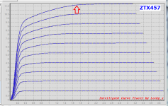
ZTX457 curves (credit again to @Mark Johnson for posting these):
I too am starting to examine this part in the Q8 position, wondering if the ZTX851 might do better. Not that I distrust anyone who has already made measurements, but the 457 looks like it might be in a quasi-saturation region at the circuit operating point. Other parameters may be superior - I haven't dug into it much.
I too am starting to examine this part in the Q8 position, wondering if the ZTX851 might do better. Not that I distrust anyone who has already made measurements, but the 457 looks like it might be in a quasi-saturation region at the circuit operating point. Other parameters may be superior - I haven't dug into it much.
Attachments
Thank you hifiZen for your great and correct contributions on the topic.
Regarding the collector circuit of (around) the Q8 (Cap-Multiplier as an analogy or synonym)-: As a non-native speaker, it's really difficult for me to explain how it works - does it make sense to explain the basics here?
Regarding the collector circuit of (around) the Q8 (Cap-Multiplier as an analogy or synonym)-: As a non-native speaker, it's really difficult for me to explain how it works - does it make sense to explain the basics here?
Everything is actually explained quite simply, but I try to simplify it in a way that is generally understandable:
R19 & R20 form a voltage divider, of course R20 is actually only intended here as a discharge resistor (I think? Wayne, I'm calling you!). Considered as a voltage source, there is now an original voltage / terminal voltage of 14.851V with a series resistance of 990.1 ohms (we call this internal resistance). This equivalent source can handle a maximum current of about 15mA (dc). It controls our Q8 statically. Q8 also functions here as a source for our discrete input stage (without the op-amp.) Simplified, we model it as RL=1kOhm (that fits), and of course the huge C6 is connected in parallel.
IL_max about 13mA and our control source is ready to pump 15mA into the base of the Q8. Q8 therefore opens fully statically. Now C7 also charges up, namely to around Vcc (see above) ..!
But that's not the trick:
C7 forms a first-order low-pass filter with our Ri (fg=0.731Hz) and this results in the remaining ripple being attenuated by slightly more than 40dB.
Q8 follows exactly this ripple at its emitter (so they say) as a dynamic input signal, but its dynamic output resistance (rbe + R21 + Ri) / (beta+1) is very small, mainly because X_C7 (jOmega) is of course only slightly more than 7Ohms.
Idealized, there is now an ideal voltage source at the emitter of Q8. The load side is reflected as a dynamic input resistance (rbe + R21 + beta * Rl) || Ri this does not load our input-side filter at all.
#
Now everyone can ask themselves which trasistor is the best in the world at this point.
Last edited:
@hifiZen,
"richtig, denn R19 ist zu niederohmig" - correct, because R19 is too low impedance. (But now we ignore the Cap C7, C7 is also working as a battery).
😢
To be honest, Vcc is a little too low for the cascode at just under 14.3V ... and so on. But, as long as it works (with ...) -
and this is Wayne's circuit and not mine or yours or Jim's or ... That's why I think it would be so meaningful if the designer or his assistant would reveal the secrets. The whys
Last edited:
Please don't get me wrong, in no way do I want to question the work and especially this circuit. It's great and perfectly fine the way it is.
kind regards,
HBt.
kind regards,
HBt.
No data needed - it's fairly straightforward theory.
Too much simulation theory and too many assumptions late at night. I need my rubber boots.
Data?
- Home
- Amplifiers
- Pass Labs
- Pearl 3 Burning Amp 2023