Hello, in the original NAIM design the offset is adjusted for a perfectly matched TR1-TR2 pair.
I myself was fooled by the AVONDALE diagram which recommended an HFE 10% higher on TR1 than on TR2...
I did that but the offset was not close to zero but several tens of millivolts (I don't remember the exact number)
This shows that their diagram is not properly adjusted, in my opinion it discredits their work.
If I remember correctly, slightly varying the value of the collector resistance of TR1 (1000 ohms) allows you to adjust the offset; we could place a variable resistor there in theory.
In practice, variable resistors sound of poor quality compared to metal film resistors and it is not said that this would not degrade the audio quality a little.
it is also interesting to measure the offset when the circuit is turned off, I noted that without the protection circuit the offset remains above 1 volt much longer when the circuit is turned off than with the protection.
These problems are usually solved by HP protection relays in the amplifiers but the NAP 250 is not equipped with them.

In the amp. Tr1&Tr2's hfe, changes the offset. But, there is no relation like %10, just like you said 🙂 I was also confused. In my design each channel have different Hfe values. One is Tr2 is lower than Tr1 and the other is NOT. Both have 0.5-2mv offset. I believe offset changes the sound/distortion.
I'm not sure changing 1k or 560ohm resistors effect the Naim sound or not. How Naim does set the offset?
I'm not sure changing 1k or 560ohm resistors effect the Naim sound or not. How Naim does set the offset?
It seems to me that you are using a modified diagram in particular with degeneration resistors, this may be why your offset remains stable whatever the HFE of the input transistors. For my part, on the original Naim diagram I have already tried and if they are not perfectly matched the offset is not optimal.
For this 1000 ohm resistor connected to the TR1 collector, Ltspice simulations showed me that its value directly affects the offset. After that only simulations remain...
I have no idea how the offset was adjusted in the original schematic; I assume it was its intrinsic design and the measurements that allowed the circuit to be adjusted at the time.
"It seems to me that you are using a modified diagram in particular with degeneration resistors, this may be why your offset remains stable whatever the HFE of the input transistors. For my part, on the original Naim diagram I have already tried and if they are not perfectly matched the offset is not optimal."
There is misunderstand due to my perfect English 🙂 I mean, tr2's Hfe changes offset. I have no degeneration resistors. my circuit just like the orginal one.
There is misunderstand due to my perfect English 🙂 I mean, tr2's Hfe changes offset. I have no degeneration resistors. my circuit just like the orginal one.
Excuse my error, my memory is obviously failing me, I thought I remembered that you used these degeneration resistors.
I use original Naim schematic (by @JeffYoung), so no degeneration resistors and no +10hfe. I matched the BC239Cs in the LTP with a cheap component tester for vbe and hfe, I get low offset of 0.5-2mV max.
Perhaps, you are not wrong. I made many Naim boards. my final choice is orginal NAP140's diagram.Excuse my error, my memory is obviously failing me, I thought I remembered that you used these degeneration resistors.
I have special question: Do you have experience for fake 2sc2922? and you changed and sound changed to ..... Or you used 2sc2922 (perhaps fake) and changed with 2sc5200/2sc3519 and sound changed to good/bad way? Thank you for share your fake or changing power transistors experience 🙂
I have no experience with 2sc2922s. I also don't have any with other references that could be counterfeits as far as the output transistors are concerned.
When I started electronics I was quickly confronted with counterfeits. Wanting to repair old devices, certain references did not exist at the usual wholesalers. So I ordered from a well-known eBay seller of integrated circuits (well-known seller littlediode and with very positive reviews)
None of these circuits worked. Another time I wanted to order from a local supplier on the internet so as not to have to pay shipping costs from the USA. New BC550Cs, they did not even work once installed in the circuit while those ordered from mouser worked. ..
So I quickly understood that outside of the big wholesalers there was no trust to be had.
CorrectI have no experience with 2sc2922s. I also don't have any with other references that could be counterfeits as far as the output transistors are concerned.
When I started electronics I was quickly confronted with counterfeits. Wanting to repair old devices, certain references did not exist at the usual wholesalers. So I ordered from a well-known eBay seller of integrated circuits (well-known seller littlediode and with very positive reviews)
None of these circuits worked. Another time I wanted to order from a local supplier on the internet so as not to have to pay shipping costs from the USA. New BC550Cs, they did not even work once installed in the circuit while those ordered from mouser worked. ..
So I quickly understood that outside of the big wholesalers there was no trust to be had.
Weight the original 2922
You are saying BC550's not work. What you mean, result was bad or transistors were dead?When I started electronics I was quickly confronted with counterfeits. Wanting to repair old devices, certain references did not exist at the usual wholesalers. So I ordered from a well-known eBay seller of integrated circuits (well-known seller littlediode and with very positive reviews)
None of these circuits worked. Another time I wanted to order from a local supplier on the internet so as not to have to pay shipping costs from the USA. New BC550Cs, they did not even work once installed in the circuit while those ordered from mouser worked. ..
So I quickly understood that outside of the big wholesalers there was no trust to be had.
Sounds to me like fake BC550’s are what wouldn’t have worked.
I wouldnt have believed fake TO-92’s either - till I got some MPAS06’s that were PNP. They didn’t work. Readings in circuit made no sense. Literally any NPN transistor, real or fake, would have worked. As long as it was NPN.
I wouldnt have believed fake TO-92’s either - till I got some MPAS06’s that were PNP. They didn’t work. Readings in circuit made no sense. Literally any NPN transistor, real or fake, would have worked. As long as it was NPN.
I think this is the answer: 47uf+47uf feedback capacitors (series with 1k) are charging. This charging & capacitor type are changing offset for half an hour.NAP140 clone works fine! I have a question output offset voltage. When turn on the amp. Offset is larger than 50mv. decreasing very fast and after perhaps half an hour after it decrease to 1mv and stay at 1 mv. How this mechanism work?
If there is no simple answer. Forget it 🙂
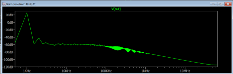
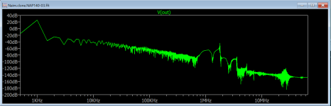
For information:

Look 0.2uf inductor. Perhaps 2,3 round cable. How important cable connections are!
Attached files are without inductor and with inductor. Ltspice simulation.
Using different power transistors, system may be more stable or not.
Look 0.2uf inductor. Perhaps 2,3 round cable. How important cable connections are!
Attached files are without inductor and with inductor. Ltspice simulation.
Using different power transistors, system may be more stable or not.
Attachments
Just wondering how people's builds are performing after a few years since Jeff put forward his design?
@JeffYoung, is yours still running?
I have to confess that my boards have been staring accusingly at me for some time now.. probably time I did something about that!
@JeffYoung, is yours still running?
I have to confess that my boards have been staring accusingly at me for some time now.. probably time I did something about that!

- Home
- Amplifiers
- Solid State
- NAP250 clone