First reason why CM is converted into DM is because the two CM input signals don’t have the same amplitude because of tolerances in the chain from Firdac to the first stage’s output.As I said earlier at least in simulation the CM suppression of stock filter is not perfect. Could it be that HF CM noise/distortion results in differential mode noise/distortion elsewhere in the filter?
Halve of the difference is converted into DM on each differential path.
Second reason, since we are talking of distortion in the low ppm range, is that CMRR of the used op-amps should be at least very high over the range up to 20Khz but also very much the same between the two amps in the first stage.
In that respect could it be beneficial IMO to use an instrumentation amp layout, with a high DM gain and 0dB CM gain, almost independant from differences between the two amps, but then the originating CM parts still have to be equal on both sides. In that case, CM rejection will be much higher
Hans
I don’t have the info on bin width available since I’m on holiday at the moment, but what I can say is that my differential LNA preamp had 130pV/rtHz noise, but added to that the two 50R output resistors from the Dac already increased this to 1.4nV/rtHz.Bin width is shown in my measurement (ADC fs 176.4kHz, FFT size 256k).
What was the bin width you used in the measurements in your report?
Teminating the input of the LNA with two 50R resistors, gave a noise level that was at least 20dB below the noise with the Dac connected.
So the noise in my spectrum is just noise from Firdac and Filter.
Hans
My thought is it increases the non-linearity of OPA IPS, via increased BJT non-linearity with increased RB and/or interaction with the OPA input current cancelation circuit.Forgetting about the hundreds of possible alternative filter topologies for a moment, does anyone understand why the common-mode loop of the original filter has a substantial influence on the differential distortion? If so, why only on the 10 kHz harmonic distortion and not on Hans's intermodulation distortion measurement?
The IMD output level I used was -3dBFS which is where clipping starts.
When you add two -3 dB tones with a beat frequency much smaller than the frequencies of the tones themselves, the peaks will be close to +3 dB. That's because there are moments in time when the two tones are both near their positive peak value or both near their negative peak value, so the sum is almost twice the peak value of one tone.
When the beat frequency is not much smaller than the tone frequencies, then it depends on the phase relation between the tones.
My hypothesis was that it is due to the output stages of the op-amps of the filter being forced in class A. With sabotaged common-mode loop, 0 V was put on the positive inputs of the first filter op-amps. The DC Thévenin voltage from the DAC core is 1.24 V, so all stages are then biased at substantial DC voltages, causing DC currents to flow through the filter resistors.
It's a hypothesis that could be tested by forcing a voltage on the positive inputs of the first filter op-amps such that their outputs end up at 0 V DC. If the distortion then still improves, it must be something else.
It's a hypothesis that could be tested by forcing a voltage on the positive inputs of the first filter op-amps such that their outputs end up at 0 V DC. If the distortion then still improves, it must be something else.

Marcel,
This is a mysterious posting, at least to me.
The CM correction opamp U8 already forces the DC output of first stage U4 a&b to zero volt by applying a voltage on their positive inputs.
And yes that means that DC currents are permanently flowing in their resistors, maybe even forcing their outputs in class A which theoretically should even help to reduce crossover distortion.
But then you finish by saying
This sounds almost like a contradictio in terminis.😊
Improving distortion by forcing an output to zero that is already forced at zero volt ?
Hans
This is a mysterious posting, at least to me.
The CM correction opamp U8 already forces the DC output of first stage U4 a&b to zero volt by applying a voltage on their positive inputs.
And yes that means that DC currents are permanently flowing in their resistors, maybe even forcing their outputs in class A which theoretically should even help to reduce crossover distortion.
But then you finish by saying
If the distortion then still improves, it must be something else.
This sounds almost like a contradictio in terminis.😊
Improving distortion by forcing an output to zero that is already forced at zero volt ?
Hans
Last edited:
When bohrok2610 sabotaged the common mode loop, the op-amp output DC bias voltages were nonzero in both the first and the second filter stages, unlike the normal case.
I made a very quick & dirty test with a bog-standard output stage in post #2125 by hooking RTZ shift register output to the output stage of one of my AKM dacs with jumper wires.
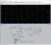
This is the actual circuit.

Here is 10kHz differential distortion of that setup.

So even with this rudimentary setup clearly better than stock filter. And no DC offset at single-ended output.
This is the actual circuit.
Here is 10kHz differential distortion of that setup.
So even with this rudimentary setup clearly better than stock filter. And no DC offset at single-ended output.
Nice ! I’ve got a twisted pear audio ivy 3 board somewhere with opa1632’s. maybe I could butcher it and try your output stage Bohrok
does anyone understand why the common-mode loop of the original filter has a substantial influence on the differential distortion?
Any differential circuit has limited CMRR, so CMNoise and CMDistortion is converted to DM disturbances at a much lower level.
In most DAC's (especially RTZ) there is a very large common mode component at the sample rate, larger actually than the signal. You might remember me mention it in our private conversation on topologies, me citing this as an argument in disfavour of RTZ.
You have two capacitors which, with the DAC's output impedance form a 53kHz lowpass, so around -46dB at ~10MHz. Not a hell of a lot, but better than nothing.
The I/U conversion OPA will be too slow to actively null the sample rate.
Here a bit of detail on the non-ideal behaviour of real Op-Amp's as I/U conversion.
So a lof of common mode sample rate switching ride through to the input of CM servo, which will also receive any error from the less than perfect circuit symmetry. What it does there will be fed back as common mode to the I/U conversion where is distorted more and ends up back at the CM servo.
In effect we see the non-ideal behaviour of real circuits.
Simple solution, restructure the circuit to use a differential I/U conversion, making sure to handle the large common mode switching noise using passive means (CLC ahead of the I/U conversion?).
Done.
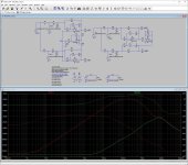
Here my frontend suggestion compared to the original WITHOUT common mode servo:
Purple and Fucsia are the respective common mode MvG test circuit's output (Purple) and normal I/U conversion virtual ground node.
Light Blue is the common mode input on my suggestion and Teal is the common mode output.
Differential (and SE Out) match pretty closely, the extra filtering in my circuit adds0.1dB 20kHz attenuation to orignal design.
Improvement in common mode rejection at I/U conversion out at 100kHz is 90dB, 55dB at 1MHz and 45dB at 10MHz.
Noise at input of the I/U conversion at 10Mhz is improved by 50dB.
And no common mode servo is needed yet DC at the I/U conversion output is 0V.
Thor
Attachments
Sorry, I strongly reject that any differential circuit has limited CMRR.
When properly designed it’s no problem to get figures of 100 to 120dB all the way up to 20Khz, only dependant on the op-amps used.
The point however is that CM output from both Firdacs have to be equal, see #2141.
No topology in the world will be able to remove CM when different levels are offered at both inputs.
The other thing is that the Firdac basicaly produces voltage and no current, so talking about I/V conversion is not correct.
So, ideally there should be a special mode to get only CM from both Firdacs.
In that case R48 or R36 can be adjusted to get the lowest signal at the output.
Hans
Last edited:
Sorry, I strongly reject that any differential circuit has limited CMRR.
55555 (in Thai 5 = Ha)
They all do.
But the point of maximising inherent circuit resilience against error signals, rather than maximise it and slap servo on as cheap band aid is well made.
Why correct after fact when you can prevent the problem in the first place?
Thor
Yes. But as Thor's (and my) simulation shows the CMRR of stock filter is not that good regardless of the CM servo opamp. If it is not good in simulation how could it be better in practice?When properly designed it’s no problem to get figures of 100 to 120dB all the way up to 20Khz, only dependant on the op-amps used.
I completely agree, but wouldn’t it be worth to understand why.
With many people having this circuit, when understanding the reason why, there is always a chance that things can be improved.
The OPA1632 that you used has a GBW of 40Mhz and a slew rate of 72V/usec versus 18Mhz and only 6.4V/usec for the OPA2210, so you are seemingly comparing different topologies with unequal op-amps.
On the other hand the OPA2210 has a fantastic CMRR of 140dB, where it is unspecified for the OPA1632.
I would love to do the simulations to compare, but don’t have a computer at my disposal here.
Besides, my wife would kill me when seeing that during our holiday I was using a computer.
🤣
Hans
In simulation the speed of CM loop opamp does not really improve CMRR. So no point in trying in practice especially since my layout uses OPA210 in SOT23 package. No fast opamps available in that package with +-15V supply.
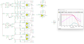
Here is my take on simulating the CMRR of stock (red) vs. Thor's (green).
Here is my take on simulating the CMRR of stock (red) vs. Thor's (green).
Attachments
Interesting,
What happens when you remove R17 and change R25 into 249R, the same value as on the minus input.
Hans
What happens when you remove R17 and change R25 into 249R, the same value as on the minus input.
Hans
That’s a rather substantial improvement of almost 20dB in the audio band.
But yes, the other circuit performs even better.
Replacing the two opamps in the second circuit by one OPA1632 would probably even furthe improve CMRR.
However keep in mind that this is with components that are absolutely ideal.
To start with, the Firdacs will have tolerances and so have the caps and the resistors.
So how realistic is this idealistic image.
Just make one 8n2 cap on both circuit 1% larger to 8n282 and see what happens.
Hans
P.s. reducing C15, the 15pF cap might improve the CMRR of Marcel’s circuit even more.
P.s2 probably even 1% is totally unrealistic and should be higher.
Last edited:
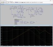
Now you are definitely on to something. Increasing one cap to 8n4 and CMRRs are similar so Marcel's CM loop has clear edge against tolerances. But whether or not that is also true in practice is the question. My test with OPA1632 stage seems to prove the opposite.
Attachments
- Home
- Source & Line
- Digital Line Level
- Return-to-zero shift register FIRDAC