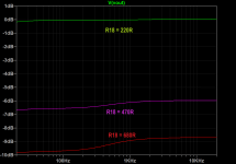
Right. Only about a dB and a half... barely noticeable.I again learned something from this last post. I made R18 270R with C8 = 100uF to get my desired LF roll of, but did'nt realise it would also alter the gain. But I guess the difference between 220 and 270 is not that big?
Perhaps it would be very beneficial if Wayne told us that the idea is that the Q5 can be fully operational, without any harm.Just a curious question regarding the cascode and saturated Q5. It was mentioned that if Q5 is saturated then you could insert a wire instead.
Has anybody tried that or simulated it?
I won't try it but if a wire is the same as Q5 saturated then R2/R3 could also be omitted?
What I would like is to read about the theory behind an amplifier with cascode.
Dear MEPER,
you can set up a simulation, for example with "Micro-Cap 12", then you can see it for yourself.
Nelson Pass once wrote a short paper on the cascode operation, why don't you
search for it ?
Regards,
HBt.

T3 = (R13||R28) * C3 = 73,822µs
T1 = (R17+R14) * C1 = 3,182ms
T2 = [(R17+R14) || (R15+R18)] * C1 = 318,56µs
The recommendation to change the value of R18 simply to raise or lower the overall amplification factor is not a matter that goes completely unpunished.
😉
T1 = (R17+R14) * C1 = 3,182ms
T2 = [(R17+R14) || (R15+R18)] * C1 = 318,56µs
The recommendation to change the value of R18 simply to raise or lower the overall amplification factor is not a matter that goes completely unpunished.
😉
C12 & R28
"... to get my desired LF roll of" [Quote Wellerman]
Welche untere Grenzfrequenz schwebt Dir denn vor? What lower cut-off frequency do you have in mind?
With the hopefully very large C8 you don't usually set a cut-off frequency, but the so-called rolloff is -20dB/decade. Correctly, the rise /slope is positive, i.e. +6dB/octave.
Basically, the lower cut-off frequency is set elsewhere inside or outside the circuit. Do you want to implement the IEC recommendation? Then the tendency nowadays is to use an active subsonic filter.
You're right, you never stop learning.
😉
Last edited:
Sorry,T2 = [(R17+R14) || (R15+R18)] * C1 = 318,56µs
C4 = 100nF is correct! T2 = (...) * C4.
😢
I found a website that let me calculate -3dB points for a high pass filter. It also gave attenuation at other frequencies. I looked for a combination (C8 R18) that would give me little attenuation in the audible frequencies (I mainly looked at 20Hz and more important 30Hz) while still having a relatively high -3dB point to counter rumble effects. I could reporoduce the corner frequencies as published in the P3 paper. With my values I could keep attenuation in the audible frequencies below -0.3dB iirc while still having a corner frequency of > 5Hz.
OK, so with 270R T2 = 322,6 uS 3100Hz in stead of 3139Hz, no idea how audible that would be ;-)
f = 1/ (2*PI*Tau)
Dear Wellerman,
now the parallel capacitor C25 has become very important.
You will ask why this is so and find it out for yourself - this is more fun and is good for the learning curve.
The PEARL three template is an ingenious trick from Wayne, a clever offer to the DIY community.
Greetings to bavaria,
HBt.
On the drawing sheet for the festival, Wayne specifies a range of 100µF < C8 < 1000µF.
In some very old EQ boxes you will also find larger values for this capacitor.
Don't worry about it - "mach Dir keine Birne, bau auf".
Enjoy your P3 - I'm always happy with my P1 (2 and 3 will have to wait a little bit longer - should they follow soon? definitely!)
🙂
In some very old EQ boxes you will also find larger values for this capacitor.
Don't worry about it - "mach Dir keine Birne, bau auf".
Enjoy your P3 - I'm always happy with my P1 (2 and 3 will have to wait a little bit longer - should they follow soon? definitely!)
🙂
Last edited:
But now you are significantly lowering the base potential, which would be one of the possible solution strategies for all BL types. If there is no metrological relevance, then you can question the cascode - but that would be a kind of unattractive.A different strategy with regards to the cascode is to make R3 4.75K. The voltage is lower on the drains but at the AC levels it isn't much of an issue.
I don't see much if any measured difference with any of these resistor or transistor changes.
However, this in no way means that you would recommend the totally saturated and reverse bias, i.e. completely conductive Q5.I just built mine per the schematic and have been listening to it since September.
The circuit topology is simply quite robust and all the LEGO bricks are attractive, you can use them or not. From this point of view, I think your idea for the 2023 BA Festival is simply brilliant. However, only a few will recognize this, which is perhaps why Mark Johnson recommends a tough announcement regarding dimensioning (and components) without any degrees of freedom.
Greetings,
HBt.
PS
The kit, the PCB, the circuit, the case ... is fine and looks very beautyful.
Last edited:
See Auricle's post #2442: https://www.diyaudio.com/community/threads/pearl-3-burning-amp-2023.404054/page-123#post-7606133Has anybody tried that or simulated it?
And also in real life.Ok, so cascode actually work in simulation.
You must include the local and global negative feedback of the stage in the calculation.But it seems that in real circuit there are no measurable difference if Q5 is saturated or not?
I think, Wayne Colburn would rather you not worry and not go round in circles.That is how I understand the feedback from Wayne.
But, after some down time, you could dimension the Pearl 3 first stage from the ground /scratch up in a new thread and explain the WHYs. Starting with the characteristic curve ID as a function of -UGS.
Attachments
Great article!
Also the one written by Nelson Pass.
The curves looks a lot "flatter" after "cascoding".
Also the one written by Nelson Pass.
The curves looks a lot "flatter" after "cascoding".
Better - we should / not you could. I mean: we all should thing twice about the first stage right from scratch.
But there is still much more to discover.
Yes 🙂The curves looks a lot "flatter" after "cascoding".
But there is still much more to discover.
Last edited:
Increasing the value of R18 will affect RIAA compliance -- it's the termination load. See the Lipshitz paper.You can raise the value of R18 to reduce the gain without altering the RIAA EQ. Swapping from 220 Ω to 680, 690 or 706 Ω will knock the gain down by ~10dB. I'd also reduce the value of C8 in proportion to maintain the LF pole. A 68 µF bipolar would be a good choice here.
Attachments
In P2 article the argument for the cascode is as copied below from the P2 article:
https://www.passdiy.com/project/preamplifiers/pearl-2
" it is used to shield the Drain of Q6 from the output voltage consequences of the input signal, lowering distortion and improving high frequency bandwidth. "
As P3 input stage looks similar I assume the argument is the same.
I modified P3 so Q5 is not saturated and I assume that the argument is only 100% valid if P3 Q5 is not saturated.
So far I am happy with that (OCD).
Let's strike while the iron is hot and stoke the fire a little more.
Let's consider (or don't) what if:
R1=590Ohm, R2=12k4Ohm, R3=8k2Ohm;
R4=R5=R6=R7=4.3Ohm, R8=15 or 18 or 22 or 27 Ohm and R10<22kOhm (with C1>1µF).
Let's consider (or don't) what if:
R1=590Ohm, R2=12k4Ohm, R3=8k2Ohm;
R4=R5=R6=R7=4.3Ohm, R8=15 or 18 or 22 or 27 Ohm and R10<22kOhm (with C1>1µF).
right - Q5 is not a switch or wire.I modified P3 so Q5 is not saturated and I assume that the argument is only 100% valid if P3 Q5 is not saturated.
Last edited:
- Home
- Amplifiers
- Pass Labs
- Pearl 3 Burning Amp 2023