Ya gotta love the beautiful industrial simplicity. Looks like something Neils Bohr might have drawn.
All good fortune,
Chris
All good fortune,
Chris
Well, the first test was an unmigitated failure!
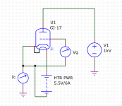
See attached test circuit. First I started with Vg at -250V and slowly turned it toward zero, expecting at some point Ic to start coming up.
No joy. Tried 2nd tube, no current at all up to Vg = 0 V.
Reversed Vg and started to turn it up from zero to positive, and saw grid current coming up. Still no Ic!
At one point I did hear/see something like a short flash inside the tube though.
I measured Va directly at the anode metal and 1kV was there.
Heater was as expected, 6A at 5.5V, nice red glow.
What am I missing??
Jan
Attachments
First use your test setup on a regular triode! Of course it should work on a known good tube. If it doesn’t either the laws of physics have changed or you have done something wrong. The other conclusion is that you purchased new old dead tubes.
I probably did something wrong. If I purchased dead tubes, how would that manifest itself?
They were in their original Russian boxes, looked unused.
Another thing I looked at is that the grid contact (which is an M6 threaded stud) has a bad contact to the test clip; it looked somewhat corroded but I DID see grid current with Vgk>0 so that contact looks OK.
Jan
They were in their original Russian boxes, looked unused.
Another thing I looked at is that the grid contact (which is an M6 threaded stud) has a bad contact to the test clip; it looked somewhat corroded but I DID see grid current with Vgk>0 so that contact looks OK.
Jan
Anode current meter broken.
I tested a module of the direct drive amp yesterday and it worked then.
Murphy at its finest.
So prelim results:
Vak 1kV
Vgk Ia
-63V 10mA
-55V 20mA
-50V 30mA
Vak 2kV
Vgk Ia
-130V 10mA
-116V 20mA
-107V 30mA
The design calls for 25mA quiescent current, with +/-20mA swing.
I am hoping that I can drive it in grounded grid with the cathode not too high in voltage.
I don't have a 4kV source right now but I hope that I can get down to 5mA Ia with no more than -250Vgk and 4kV Vak.
We'll see.
First test looks promising right now.
Jan

Oh by the way, as the voltages you are using can be lethal, take care! Of course you would not play with such high voltages without some one else around to call for help!
Of course not! And no watches, rubber soled shoes, one hand in the pocket.
And I need to throw three switches before the HV comes on.
I started my career working on 25kV color TV power units.
As they say, good practise comes from experience, and experience comes from bad practise.
Knock wood.
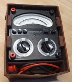
Edit: Time to break out the 3kV DC/AC vintage AVO I scored last year at the ETF!
Jan
And I need to throw three switches before the HV comes on.
I started my career working on 25kV color TV power units.
As they say, good practise comes from experience, and experience comes from bad practise.
Knock wood.
Edit: Time to break out the 3kV DC/AC vintage AVO I scored last year at the ETF!
Jan
Attachments
Last edited:
So mu is almost 17 rather than 10, at 25 mA anyway. About 225 V peak cathode voltage swing should do to get 4 kV peak anode voltage swing.
I think I can handle that.
Use a HV FET or BJT in the cathode current driver can easily handle up to 500V cathode compliance with just a few Watts of dissipation.
The tube will dissipate around 80W which is about half of the 150W max.
I wonder if it will need forced air cooling.
Jan
Use a HV FET or BJT in the cathode current driver can easily handle up to 500V cathode compliance with just a few Watts of dissipation.
The tube will dissipate around 80W which is about half of the 150W max.
I wonder if it will need forced air cooling.
Jan
Jan you definitely need to provide forced air cooling, both for the tube anode and the grid, how the grid cooling is made for professional CCS use is described in post #205,
in any case, under all conditions of tube use the temperature of the anode must not exceed the prescribed 140 degrees Celsius.
in any case, under all conditions of tube use the temperature of the anode must not exceed the prescribed 140 degrees Celsius.
Yes, I hope with the reduced Pa and smart construction I can keep it below 140C without forced cooling.
Jan
Jan
That 225 V peak is not taking into account the current through the loudspeaker, by the way. I just assumed a constant 25 mA anode current.
Not sure I get that Marcel. The current swing through the speaker are 20mA pk, so for class A the bias current is 25mA.
All approximate, will be refined at design time.
Jan
All approximate, will be refined at design time.
Jan
Good thing mu seems on the high side, but you may want to shunt your cathodecurrent meter with some 10nF mica cap in case the tube breaks into oszillation. Also, a sturdy ww resistor in the cathode circuit, could be worth using (just for safety, should the cathode circuit go open, tube flash over or anything that could take out the meter).
Last edited:
Not sure I get that Marcel. The current swing through the speaker are 20mA pk, so for class A the bias current is 25mA.
All approximate, will be refined at design time.
Jan
The loaded voltage gain of the common-grid stages will be 1 + gm ZL ri/(ZL + ri), where gm is the transconductance of the valve, ZL the load impedance per side, so half the differential load impedance, and ri the valve's internal resistance. I forgot to take the ZL into account.
Looking at your measurements, the ri term dominates. You maybe need 30 V or so more than I calculated.
Propable what took out your meterAt one point I did hear/see something like a short flash inside the tube though.
140ºC doesn't seem very high for an upper max. Is that to protect the seals or prevent thermal runaway?the temperature of the anode must not exceed the prescribed 140 degrees Celsius.
- Home
- Amplifiers
- Tubes / Valves
- Looking for high-voltage tubes