Yes,Ed, just out of curiosity, did anything of interest came out of the fuse tests?
Jan
Fuses from some manufacturers are extremely inconsistent when purchased at different times. At first I thought I would need to test under 100 samples to get useful data, it now looks like sample size may rise to 1000+! So it will be a lot longer to complete the research. Also a bit busy at the moment.
The current conclusion is to only buy established name brand fuses.
My first experience with fuse failure came at a baseball park. Some of the low power gear would blow fuses after operating for months. Had to install higher current fuses to keep the system running! Of course had to measure current draw first. Not easy as one would assume!
Corona is ionisation of the air, yes, but it is fieldstrength dependend, so the further from ground the smaller will be the fieldstrength with a given radius, no?
Anyway, corona can exist undetecable by eye, but that is of minor importance.
Important is to keep the average fieldstrength safely below 4kV/cm to prevent high power discharge channels.
In my 40+ years expirience with 6-12kV transmitting tubes (industrial rf-heaters) i found a distance of 1cm/kV
to be plenty enough to prevent serious discharges.
(some occasional flashmarks still possible, but nothing serious enough to damage components or interrupt production)
Discharge distance is changed by a humid day! I have seen a demonstration from a fellow with a screwdriver learning what was safe to do in the winter was not come summer! Fortunately low enough current that he survived the lesson.
1 KV per CM seems to me to be reasonably cautious!
So far have only lost one friend from carelessness. Perhaps why I am a bit more cautious than some folks here.
1 KV per CM seems to me to be reasonably cautious!
So far have only lost one friend from carelessness. Perhaps why I am a bit more cautious than some folks here.
Purchased a bunch of these. Was a good tip. New they are $ 250 each.Posting capacitors to help with this is just gonna enable Jan to actually do this crazy project. Are we really sure we want to do that?
Yes! Yes we are! To wit
https://www.surplussales.com/item/_CFP/c44f8ez6100za0j.html
Two in series with proper balancing resistors should be good for 4kV.
And I blew a heater supply, after I heard a discharge.
No idea what happened, maybe I should get proper HV cabling ...
Jan
Attachments

The fact that they must be able to deliver amperes of Ia (albeit short pulse) is the reason for the relatively high heater power.Jan
there`s no any beam plates on GMI-83 or by type -83V , by GMI-83 it is just ordinary horizontally winded wires both for g1 and g2 grids , but by model GMI-83V grids wires are vertically parallel stacked forming wired cage around huge round cathode ,
btw, IMHO what`s important to notice is the fact that anode Pd-max is only 60W , so let`s say by B+=4000V and steady Ia=0,015A (15mA) anode will reach the limit of full anode metal plate disipation of 60W , (4000V x 0,015A = 60W) , so any anode current above constant 15mA will made thin anode plate to run red hot , which IMO is not good,
it is interesting by these types of pulse tetrode tubes that those mighty cathodes are capable to emit electrons pulse flow in amperes ranges , where anode plates are relative low power limited , but in the same time very unlimited for max. anode voltages which can be in range from 18KV up to 20KV.
Those high anode currents need a lot of electrons in a short time. But the average power dissipation is low.
Jan

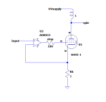
Adrian Immler from Austria was so kind to put an LTspice model together for the GI-17.
It looks like a reasonable match to my measurements.
I have modified my current amplifier model based on the 6HS5 and next will see if I can port the GI-17 model into it.
The original design used the 6HS5 in grounded grid, driven with a cathode current.
With the GI-17 that is complex as the heater supply is connected at one side to the cathode so will swing the parasitic capacitances, which causes losses.
I now want to drive the GI-17 at the grid, but with feedback from a small sampling resistor in the cathode lead to remain in current drive mode.
This way the triode will look like an (ideal) pentode.
Exciting!
Jan
JanPurchased a bunch of these. Was a good tip. New they are $ 250 each.
Two in series with proper balancing resistors should be good for 4kV.
And I blew a heater supply, after I heard a discharge.
No idea what happened, maybe I should get proper HV cabling ...
Jan
IMHO you can check in yours local automotive shops for those 7mm in diameter spark plug silicone cables with insulated cooper stranded wire in the center ,those HV cables can be good choice for your amps , think that those cables are good for at least 20KV if not way more .
Attachments
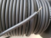
Just watch out for some spark plug cables have built in resistance of maybe 10K per foot or so.
Yes I know that there`s some spark plug cables with built in resistance, but those types of cables does not have cooper stranded wires in the center but something like graphite .
This guy has all I need: https://www.benl.ebay.be/str/highvoltageshopc0m
And he is in my back yard ;-)
Jan
And he is in my back yard ;-)
Jan
This is my current amplifier:
https://audioxpress.com/article/you-can-diy-edd-a-direct-drive-amplifier-for-electrostatic-speakers
Jan
https://audioxpress.com/article/you-can-diy-edd-a-direct-drive-amplifier-for-electrostatic-speakers
Jan
Thank you for that write up! And for putting your life on the line handling potentially lethal voltage and current combinations. Somewhere I remember it's not the voltage that kills, it's the current, and the most lethal for the human heart are between 100 and 200 mA. I'm not sure I could trust myself to work single handedly, I'd slip up at some point or another. A friend of mine used to work with high voltage transformers in the nuclear plant business and made a mistake at one point. He was literally thrown backwards a few meters. Great to see the comparative distortion measurements, too. I can't remember that I've seen a comparison like that before. You mention very high SPLs, could you measure those as well?
Jan,
check out this pdf (vol 5, Glasoe and Lebacqz), <www.introni.it >pdf>05-Pulse Generators
Starting from page 106 it is about vacuum tube properties for use in high voltage pulse generators.
At the time, there where no special "impulse" type tubes yet, so they investigated
"radio" tubes that could handle, a.o.t., the high anode voltages needed for pulse radar
Last edited:
@gorgon53, I don't see any PDF on that page, or in the left side menu.
Nothing I see is about pulse generators.
Is it possible to download the PDF and send to me or send a link when it is open?
I'm definitely interested.
Edit: Google found it, it is a book by Glasoe and Lebacqz.
Definitely interesting. Thanks for the tip,
Jan
Nothing I see is about pulse generators.
Is it possible to download the PDF and send to me or send a link when it is open?
I'm definitely interested.
Edit: Google found it, it is a book by Glasoe and Lebacqz.
Definitely interesting. Thanks for the tip,
Jan
BTW, does anyone have some characteristics of the CV-381?
Negative Vgrid for cut-off?
Anyone have a source for this tube?
Jan
Negative Vgrid for cut-off?
Anyone have a source for this tube?
Jan
@Tubelab_com: George, reading thsi again, see the attached from the Beveridge direct drive amp. Vg2k is 36V and apparently that is enough for this application.I never tried running a good sized tube with zero or negative voltage on the screen. Most pentodes, especially big ones, will need some positive voltage on one of the grids to get some current flow. The current drawn by G2 will be very low if the plate voltage remains considerably higher than the screen voltage. You aren't looking for a lot of plate current, so maybe a few volts on G2 will be sufficient? Will your circuit work if the G2 current is supplied by an independent floating supply between the cathode and G2? If so, then that's not too hard to do.
Maybe I should check that out.
Jan
Attachments
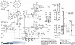
The beam regulator triodes like the 6HS5, 6HV5 and others are essentially a sweep tube with the screen grid left out. In my experiments using them on 650 volts a positive grid voltage was needed to get reasonable plate current. The high Mu (300) and Gm (65000) of these tubes makes them prone to spurious oscillation with my clip lead construction techniques. With 3500 volts on the plate (max spec is 5500) you will be in negative grid region and within the range of an opamp chip. Curves are furnished in the 6HV5 data sheet. The other variants 6HS5, 6JD5 and 6JK5 are similar, but often cheaper. These come in two plate sizes, 30 watt and 35 watt. I have seen both size plates in tubes with the same type number on them.
- Home
- Amplifiers
- Tubes / Valves
- Looking for high-voltage tubes