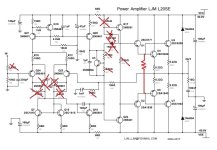
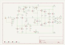
The circuit can be brought to its original form as it was originally conceived, where the Douglas Self circuit operates as a voltage amplifier, and the Lokanti power stage is the output.
I have highlighted in red unnecessary elements and denominations that worsen the performance of this scheme.
The resistor drawn in red is necessary because it forces the U1U2 stage to operate in linear mode, and also does not allow through current through the power transistors at maximum signal.
Also in the attachment is an already corrected version of both the formation of stability inside the amplifier and under a complex load, pay attention to the values of the Thiel circuit at the output of the circuit.
Attachments

Last edited:

Thank you for your feedback @Hennady.
Regarding the miller cap, as I've had no instability issues, I'll probably swap it back for the 100pF it was supposed to be next time I get the amp opened up for painting and finishing.
I see your point both on the gain and input stage. My DAC is based on a MS8412, it has a local 3.3V regulator, I'll check if it's VAA is operated at 5 or 3.3V. Output swing peak to peak is rated at 0.65x VAA, so I eiter get 3.25 or 2.15V PP clipping output. I haven't used the amp that much at full power to notice any distortion or clipping yet, at least by ear. In the future I want to get my oscilloscope back running and I'll do some proper tests with a dummy load on the amp. Volume is usually higher than about half, I tend to do some control also on the PC. I shouldn't get too affected by a low input resistance divider (potentiometer) throwing the RC input filter out of whack.
Later I'll toss your revised 2024 design into multisim and post the files here. Have you got an amp built on that version yet?
ok, I’ll try to calculate the correct value of the Miller correction, taking into account that stupid 33k resistor on the positive supply rail, through which power noise penetrates the input of the output stage, while it limits the gain of the driver transistor and speeds up the limitation of one half-wave in relation to the other..Regarding the miller cap, as I've had no instability issues, I'll probably swap it back for the 100pF it was supposed to be next time I get the amp opened up for painting and finishing.
I shouldn't get too affected by a low input resistance divider (potentiometer) throwing the RC input filter out of whack.
you can bypass it with 22Kohm resistors (approximately, you can pick it up by ear),from trimmer input to middle output and from middle output to ground.
Yes, I have modified amplifiers for my friends using boards from this manufacturer. It can be said that all versions of his amplifier boards need improvement, while the original versions of circuits that he takes for cloning are actually of very good quality, and the modification of stability correction occurs due to the fact that the quality of the elements and acoustics have become better, and The mathematical apparatus of analysis has also been improved.Have you got an amp built on that version yet?
P.S. On the forum somewhere there is a photo of the amplifier that I myself assembled from its boards.
Thanks Hennady, this is very useful info and it seems the 33k resistor to VCC explains my issue with PS harmonics on the output. I was going to try filtering the supply further or add a separate regulated supply to get rid of it but if what you are sharing really works I am inclined to make your suggested changes.The circuit can be brought to its original form as it was originally conceived, where the Douglas Self circuit operates as a voltage amplifier, and the Lokanti power stage is the output.
I have highlighted in red unnecessary elements and denominations that worsen the performance of this scheme.
The resistor drawn in red is necessary because it forces the U1U2 stage to operate in linear mode, and also does not allow through current through the power transistors at maximum signal.
Also in the attachment is an already corrected version of both the formation of stability inside the amplifier and under a complex load, pay attention to the values of the Thiel circuit at the output of the circuit.
As is mine measures ok'ish THD/IMD wise at normal listening levels, not great noise wise due to the PS harmonics ofc.
Any idea why these changes were made if the original design was already good enough?
Make changes as soon as possible and enjoy the sound of your amp.if what you are sharing really works I am inclined to make your suggested changes.
I tried to explain to him why it was bad to do this, he couldn’t explain anything intelligible, apparently he just doesn’t have enough knowledge and design experience yet.Any idea why these changes were made if the original design was already good enough?
In any case, you still need to understand that this is the level of an average high-fi, by installing a emitter follower front of the driver, and not in the diff stage, distortion can be reduced by an order of magnitude, i.e. by a factor of 10, and increase linearity to negative feedback coverage. This will allow you to better feel the subtlety of the sound of acoustic systems, especially reference ones, more clearly visualize the stereo soundstage and more clearly define the ideas of the recording engineers.As is mine measures ok'ish THD/IMD wise at normal listening levels, not great noise wise due to the PS harmonics ofc.
I kinda like bright highs in music, I listen to a lot of rock, metal, fusion and some other genres and I don't want to hear dulled or flat cymbals or hats. My speakers are decently linear, with impedance slowly rising above 5KHz (Indiana Line Tesi 261). Compared to other speakers I've heard in similar conditions, mine do feel a bit less "bright" than others.Glad it all worked out! Nice work! Any Top end brightness?
This is a thing I've seen discussed in several forums. It's likely to be also related to the amplifier's resolution and slew rate ad higher frequencies, as what we perceive as brightness and top-end clarity is probably related to the amplifier ability to represent those fast parts of the signal without distortion or loss of gain. If anything, with this amp compared to other [less accurate] devices I feel a lot more bass, overall depth and wider sound stage.
The circuit can be brought to its original form as it was originally conceived, where the Douglas Self circuit operates as a voltage amplifier, and the Lokanti power stage is the output.
I have highlighted in red unnecessary elements and denominations that worsen the performance of this scheme.
The resistor drawn in red is necessary because it forces the U1U2 stage to operate in linear mode, and also does not allow through current through the power transistors at maximum signal.
Also in the attachment is an already corrected version of both the formation of stability inside the amplifier and under a complex load, pay attention to the values of the Thiel circuit at the output of the circuit.
As promised I've drawn your design in Multisim, and the preliminary results are very interesting. Only small modification I did is splitting the bias pot into two resistors and a smaller potentiometer, as very small adjustments would yield very high bias current changes. It's attached inside a zip file.
The modifications are mostly very simple, as they involve mostly removing "unnecessary" parts added in LJM's design. Had I found your schematic while I was building the amp I would have probably done all these mods straight away. I'm tempteded to redo the pcb entirely for your design, and have it outsourced to any of the major board prototypers for a quick build. I found a store locally that has most of the active parts needed plus certainly genuine 2SC5200 and 2SA1943 at really good prices. I have another very similar transformer and enough parts to build another one, so who knows what might happen...
....
Any idea why these changes were made if the original design was already good enough?
If you read back in this thread and the other linked at the beginning of this one, LJM does seem to give very brash explaintions to his design choices, very little argumentation on why he's picked certain choices of components. If anything, at least in this thread his presence has been mostly related to "helping / pushing" people distinguish from "fakes" or "clones" to improve his sales rather than improve the circuit itself. In the other thread he says he built Douglas Self's circuit (probably the Blameless amplifier?) and he changed as it wasn't stable (!?!?!?). If you look at the deisgn Hennady posted earlier, it's extremely similar to it, with only minor modifications.
http://www.douglas-self.com/ampins/dipa/dipa.htm#6
I don't know if it's the language barrier between him and us, lack of knowledge, or lack of willingness to study the "sacred tomes" of audio design to get the fundamental principles for these devices right.
Attachments
Miller's correction cannot provide your desires. For a variety amplifier, this correction is suitable because There are additional frequency adjustments; for home listening from a high-quality source, additional frequency adjustments are not needed, but the Miller correction is already an attavism of high-quality audio amplification.I kinda like bright highs in music, I listen to a lot of rock, metal, fusion and some other genres and I don't want to hear dulled or flat cymbals or hats.
In fact, this is not entirely true; a high slew rate of the signal is necessary primarily for the operation of the output stage in class AB, and was relevant in the late 70s, because high speed makes it possible to minimize the distortion of complementary transistors, when the load characteristic changed when switching power transistors. Now, when selecting pairs of output transistors and the ability to obtain greater linearity of the voltage amplifier before covering the negative feedback, the desire to obtain the maximum possible slew rate is no longer relevant, and therefore a certain a throwback for audio lovers to vintage amplifier products with a modern element base.This is a thing I've seen discussed in several forums. It's likely to be also related to the amplifier's resolution and slew rate ad higher frequencies, as what we perceive as brightness and top-end clarity is probably related to the amplifier ability to represent those fast parts of the signal without distortion or loss of gain.
Yes, this is a slightly later version of Douglas, where he added a TR12 emitter follower, this option is more linear, and the HF distortion is 10 times (-20dB) less....If you look at the deisgn Hennady posted earlier, it's extremely similar to it, with only minor modifications.
But there is one thing where Self also makes mistakes - this is C4, which is not advisable to make a large-capacity electrolyte, i.e. you only need 1 μF (no more) and the absence of a 1k-1.5 kOhm resistor in the TR12 collector, which makes it easier to recover from overload when the signal is limited. There is also no input filter for the signal.
Returning the capacity from 300pf to 100pf, unfortunately, will not change anything for the better.I'll probably swap it back for the 100pF it was supposed to be next time I get the amp opened up for painting and finishing.
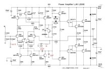
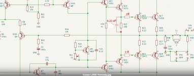
Try to do it as in the attachment - and the slew rate will be higher and it will be easier for the amplifier to “breathe” at high frequencies.
Correction changes are highlighted in red.
Attachments
Not sure I understand this fully, r u saying add the equivalent of resistors R12 and R24 below?In any case, you still need to understand that this is the level of an average high-fi, by installing a emitter follower front of the driver, and not in the diff stage, distortion can be reduced by an order of magnitude, i.e. by a factor of 10, and increase linearity to negative feedback coverage
Why? these resistors limit the base current, and this the current to control the output stage needs, then the question is why limit?Not sure I understand this fully, r u saying add the equivalent of resistors R12 and R24 below?
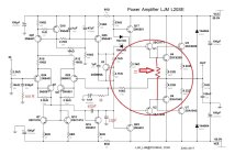
Also, in Self’s circuit, these resistors were part of the current protection of the output stage, then the protection was removed, but for some reason the resistors remained, and for about 50 years now they have been migrating from circuit to circuit. The only benefit from them is additional correction for RF due to the capacitance of the collector-base junction of transistors TR6 TR7, but this is rather a side effect, because when installing an additional RC circuit at the input of the output stage instead of these resistors in the bases, it improves the microdynamics of sound reproduction.
Last edited:
I was simply trying to understand were and how to add the resistors you referred to earlier, this was what I found and for simplicity I included the schematic. It was not to argue one way or the other.Why? these resistors limit the base current, and this the current to control the output stage needs, then the question is why limit?
For which circuit option did I say to add resistors? for LJM L20SE or Self variant?I was simply trying to understand were and how to add the resistors you referred to earlier, this was what I found and for simplicity I included the schematic.
I assumed your modded version and with your question I now think you were just pointing out the benefit of adding R22?For which circuit option did I say to add resistors? for LJM L20SE or Self variant?
You are a little inattentive, or there are difficulties with translation. If you look at my version of the circuit (probably referring to R23), I initially took a proven design, where resistors were installed since the development of Lokanti in 1967 year.I assumed your modded version and with your question I now think you were just pointing out the benefit of adding R22?
Attachments
I think its a bit of both but yes in my mind it was R23 but I wrote R22. All good now and thx again.You are a little inattentive, or there are difficulties with translation.
Hi Hennady,
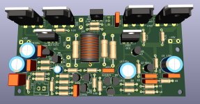
i am not satisfield with the sound of the original L20SE. The sound is loveless, no brilliance. Other amps, as the L20.5, sound much better. I dont know very much about electronic in amps, but i can draw...
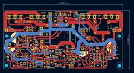
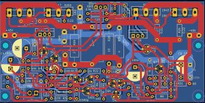
So..i took your schematic and made a pcb with KiCad. Dont know in the moment if the drivers are fit correctly to the old pcb of ljm. But changig that a little bit is no problem. To make the pcb was a bit difficult because of the big inductor and big resistors at the amp output... dont know if 5 watt are needed.
I added four things to the pcb. 3 capacitors and one resistor. The resistor 10 ohm splits the powerground to an A ground. Dont know if nessary. Three 100 nF capacitors added to the tne bigger 100 µf capacitors to posive and negativ rails. I have marked the items with a red point.
I do not share the zip file in the moment. Perhaps i have to do any changes.
You can take a look to the three pictures. i hope everything is right. I found no mistake in my drawn schematic, drc examination was ok, without mistakes.
The testpoints i need to solder 6,3 mm faston in. A little trick. I dont hve to draw faston 6,3 mm by myself...
Perhabs you can have a look ?
Greetings
Peter
i am not satisfield with the sound of the original L20SE. The sound is loveless, no brilliance. Other amps, as the L20.5, sound much better. I dont know very much about electronic in amps, but i can draw...
So..i took your schematic and made a pcb with KiCad. Dont know in the moment if the drivers are fit correctly to the old pcb of ljm. But changig that a little bit is no problem. To make the pcb was a bit difficult because of the big inductor and big resistors at the amp output... dont know if 5 watt are needed.
I added four things to the pcb. 3 capacitors and one resistor. The resistor 10 ohm splits the powerground to an A ground. Dont know if nessary. Three 100 nF capacitors added to the tne bigger 100 µf capacitors to posive and negativ rails. I have marked the items with a red point.
I do not share the zip file in the moment. Perhaps i have to do any changes.
You can take a look to the three pictures. i hope everything is right. I found no mistake in my drawn schematic, drc examination was ok, without mistakes.
The testpoints i need to solder 6,3 mm faston in. A little trick. I dont hve to draw faston 6,3 mm by myself...
Perhabs you can have a look ?
Greetings
Peter
Attachments
Last edited:
Hello Peter.Dont know in the moment if the drivers are fit correctly to the old pcb of ljm. But changig that a little bit is no problem. To make the pcb was a bit difficult because of the big inductor and big resistors at the amp output... dont know if 5 watt are needed.
Remove the Thiel coil from the board, because If your PCB layout has a large circuit, it will greatly affect the coil. Those. The Thiel coil will need to be soldered to the output terminals of the amplifier on the speakers.
5 watt resistor - ok.
you also need to add 2 resistors to the bases of the output transistors and capacitance, see attachment
Attachments
- Home
- Amplifiers
- Solid State
- Power Amplifier LJM L20SE