
Nice, and I hope you have realized that drivers Q10, Q11 and Vbe sensor Q12 must be placed on the heatsink, not in the free air. (Part numbers according to post #1)if someone wants a design in this form, lay in the archive


Measurements into the combined complex load as follows:

Load impedance

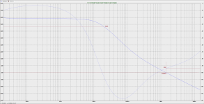
Frequency responses and THD vs. frequency


Load impedance
Frequency responses and THD vs. frequency
of course, there are holes on the board, as well as the output transistors. the board is located parallel to the radiator (suddenly someone did not understand)Q10, Q11 and Vbe sensor Q12 must be placed on the heatsink

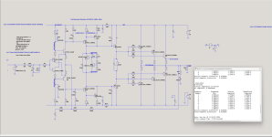
I have these results in LTspice. As for me, the phase margin is huge, you can squeeze, reduce distortion.
can you posted your .asc file?
Guys, I have repeated it many times! Do not blindly believe in simulation results regarding stability! I have played with this circuit since 2017 and I know how it behaves in a real world.
With this load


all simulators I Have (LTspice, MC11, standard models, Cordell models) say that the amp is instable, oscillating and has loopgain phase shift of some 225°. In the real world, the amp is totally stable. Here is the comparison with NC252MP, that should be OK but in fact is instable as a hell

Even into a resistor load (something that never exists as a real speaker), all simulators and models give different stability results. So please, kindly do not give me any suggestions based on your simulations. I will NOT follow it. I am an experienced engineer who designed, built and measured hundreds of circuits and I would never stick with simulation results only. Never.
yes, of courcecan you posted your .asc file?
I agree that you cannot blindly believe the simulator, but you can find ways to improve it and, if they are not too laborious, check it in hardware. Suddenly it will really get better.built and measured hundreds of circuits and I would never stick with simulation results only. Never.
you can always overlook or miss something, even from 2017...
However, if not, then, as they say in Russia:
"They don't judge for no"
Attachments
I agree that the simulator is a good 1st approximation and as such it saves a lot of time. That’s it. Nothing less, nothing more.
have you always had such a strong discrepancy between the simulator data and reality? Very much? Even with good models?Nothing less, nothing more.
That's not nice ! This is a very good design. I use this type CFA on my "Hellraiser" (running the EF3) - 20ppm/20Khz and more stability with less miller CAt this point I don't see any reason to build this amplifier.. We have better amplifiers that are worth building. (SA2014, Wolverine, FukAmp)
than the Wolverine. I built one and forgot the VAS compensation , it still did not oscillate.
I like how the old slow MJL21193/94 still have a use.... Not sure how the low Ft would affect CFA slew , this design can do >300V/us with NJW1302/3281's.
OS
I agree that the simulator is a good 1st approximation and as such it saves a lot of time. That’s it. Nothing less, nothing more.
I did read a review from the 70s of an average amp built by Onkyo, the reviewer measured the amp at 0.06-0.07% THD at 1kHz on 4R and 100W, out of curiosity i simulated the amp using the original parts 2SA1302/2SC3281 power devices, the simulator yielded 0.064% THD, that s much better than just an approximation.
Guys, I have repeated it many times! Do not blindly believe in simulation results regarding stability! I have played with this circuit since 2017 and I know how it behaves in a real world.
With this load
View attachment 1260075 View attachment 1260076
all simulators I Have (LTspice, MC11, standard models, Cordell models) say that the amp is instable, oscillating and has loopgain phase shift of some 225°. In the real world, the amp is totally stable. Here is the comparison with NC252MP, that should be OK but in fact is instable as a hell
View attachment 1260077
Even into a resistor load (something that never exists as a real speaker), all simulators and models give different stability results. So please, kindly do not give me any suggestions based on your simulations. I will NOT follow it. I am an experienced engineer who designed, built and measured hundreds of circuits and I would never stick with simulation results only. Never.
It is stable, apparently, because of the way it is built, there s about 0.4 metre total length for the speaker cables that goes from the amp circuit to the output connectors, this amount to about 1.3uH serial inductance with your dummy load, and since 0.5uH are enough to get the amp not oscillating in this load you think that it s unconditionaly stable, wich is not the case at all.
Actually simulators are accurate for estimating intrinsical stability, it s just that you omitted to take account of the parasistic components in the physical implementation wich compensate for the amp lack of stability, that s a school case of conditional stability, personaly i wouldnt be satisfied with such random conditions, but if it s enough for you so good.
Last edited:
It’s an order of magnitude less or about 120 nH.there s about 0.4 metre total length for the speaker cables that goes from the amp circuit to the output connectors, this amount to about 1.3uH serial inductance
The main mechanism for distortion is the exponential relationship between current and voltage. Real transistors closely follow the exponential, and so the simulation produces accurate results.I did read a review from the 70s of an average amp built by Onkyo, the reviewer measured the amp at 0.06-0.07% THD at 1kHz on 4R and 100W, out of curiosity i simulated the amp using the original parts 2SA1302/2SC3281 power devices, the simulator yielded 0.064% THD, that s much better than just an approximation.
I expect that Hfe variation with Ic and dynamic effects are less accurately modeled. Temperature effects are typically not simulated. An increase in bias with temperature greatly affects distortion.
Ed
It is stable, apparently, because of the way it is built, there s about 0.4 metre total length for the speaker cables that goes from the amp circuit to the output connectors, this amount to about 1.3uH serial inductance
Sorry, your calculation is wrong

https://www.allaboutcircuits.com/tools/parallel-wire-inductance-calculator/
Again, common free simulators do not show loopgain stability with complex load properly. They also do not show large signal step response properly a they do not show distortion quite exactly. Transistor models available for free are not accurate enough. Scott Wurcer stated that many times and explained that they worked with much more accurate models. We are in DIY sphere, with amateurish approach. This is not a professional world. That is fine, but the limits should be taken into account.
BTW, addition of wire inductance to the loopgain simulation was the first thing I have already done before, not surprisingly.
I appreciate the inputs, but I do not appreciate assumptions that I would behave like a 15 years old beginner in circuit analysis.
You did implement 5mm distance between the two conductors, in your pic the cables are stuck together at one mm distance, that s typically setting the wrong parameters to be on point.
That being said i m not saying that you acted as a 15 years old but you ll agrre that lots of confirmed engineers did a blunder
here or there, otherwise the debate about amps would be over for ages.
If the simulators tell you that it can oscillate then check why it s not the case in real world, it s too easy to brand the simulator
as being incompetent, they are accurate at predicting frequency responses and stability margins, actually they are even quite
forgiving in this area and often real world is not as rosy as simulation, precisely because all real world parameters are not accounted.
Last edited:
- Home
- Amplifiers
- Solid State
- PMA CFA - current feedback power amplifier with +/-25V to +/-55V dc supply range