The input stage isn't usually run very hot maybe 20db at most, your THD measurements for both channels wont be the same (Which BC546 are you using). Dartzeel in their non switching amplifier for midrange and highs does 20db for input stage. The amplifier output is self protecting from overcurrent and is biased around 100mA
Sorry, I do not understand what you would like to say and what is the meaning of "The input stage isn't usually run very hot maybe 20db at most". I also do not understand why THD of both channels should differ. The measurements do not support your hypothesis.
I am setting dc voltage across 0R22 emitter resistors of power transistors to 15mV - 22mV, which makes idle current of 68mA - 100mA per transistor.
BTW, I would like to mention that I dislike the Dartzeel amplifier and to me its output stage with the only one pair of power transistors is heavily under-sized. My philosophy is opposite, I prefer to make output stage robust with enough current capability. Like also in this amplifier:
https://pmacura.cz/pa2.htm
A small lot was built in 2010-2011 and it was pretty successful, the amplifiers are running without issues by nowadays.
Last edited:
What do you find are the reasons for the differences?And as always, simulated result is more optimistic than the real life result.
I think that the simulation assuming perfect matching, particularly between complementary pairs, eliminates the even harmonics that imperfectly matched devices will produce.
Ed

IMO simulation is only as good as are the component models. Models may be done pretty good in case of passive devices, including their parasitic impedances. Maybe not so perfect in case of electrolytic capacitors - we need to add temperature dependence and nonlinearities in electrolytic dielectrics.What do you find are the reasons for the differences?
I think that the simulation assuming perfect matching, particularly between complementary pairs, eliminates the even harmonics that imperfectly matched devices will produce.
Ed
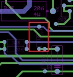
It is worse with active devices. You may send 10A current to BC547 and the model is still happy. It will only say "hot". It will not blow as a real part. The simulator would not warn you in case of parasitic 250MHz oscillations in a preamp, as seen below:

In case of power transistors, we have LTspice bjt models, we have Bob Cordell models, we have MC models and all give different results when you start to push the transistor to its limits and you will also find differences when investigating loopgain. They are also not very reliable regarding HF nonlinearity.
MOSFET models are worst regarding accordance of simulated and real parameters.
Not speaking about PCB tracks impedances, mutual inductances and stray capacitances.
That said, I am not against simulation. Simulation is a great help, saving a lot of time, but it is only a first step in the project design process. Definitely not the final step.
Why is that?At this point I don't see any reason to build this amplifier.. We have better amplifiers that are worth building. (SA2014, Wolverine, FukAmp)
Nice project. I was a bit confused at first, as I did not see the 15V for the input transistors.
I thought you forgot some zeners on your schematic ☺️
Looking at the compensation, I see no miller, tmc or tpc.
I do see the rc-network R27/R28 and the caps C14/C16 that goes with them.
I am wondering about C1 and C2. I've seen this before, but haven't quite understood how this works. Assuming the PSU is low impedance, would it not be the same if they where connected to gnd then?
Thanks for your clarification. I meant input stage gain, but then again your chosen gain should be also fine, there are amps that are pretty hot in the input stage for various reasons. See this https://www.diyaudio.com/community/threads/morpheus-ultra-low-thd.406485/post-7547805 and this https://www.diyaudio.com/community/threads/myths-tricks-and-hey-thats-neat.406418/post-7535493Sorry, I do not understand what you would like to say and what is the meaning of "The input stage isn't usually run very hot maybe 20db at most". I also do not understand why THD of both channels should differ. The measurements do not support your hypothesis.
I am setting dc voltage across 0R22 emitter resistors of power transistors to 15mV - 22mV, which makes idle current of 68mA - 100mA per transistor.
BTW, I would like to mention that I dislike the Dartzeel amplifier and to me its output stage with the only one pair of power transistors is heavily under-sized. My philosophy is opposite, I prefer to make output stage robust with enough current capability. Like also in this amplifier:
R18????
Attachments
Originally there was no C22 and R18 was in series with R19. After tests of the prototype, C22 was added in parallel with R19 and R18 was shorted by wire jumper. The PCB was no more modified then.
There are amplifiers with lower distortion, yes.At this point I don't see any reason to build this amplifier.. We have better amplifiers that are worth building. (SA2014, Wolverine, FukAmp)
But this CFA have other qualities. So, it is well worth to build.
It is the best current feedback amplifier I have seen at forum.
@PMA has delivered a serious project with testing and PCB files.
Thank you, @lineup . Everyone can make his choice which amplifier to build, it is a free will. This amplifier does not have the lowest distortion and does not have the highest slew rate of all amplifiers. As you have said, it is a long-term tested and verified design and project. With adequate parameters for music reproduction within human audibility limits. And, again, nobody is forced to build it.
This is very good CFA, but you could check those too: https://www.diyaudio.com/community/threads/200w-mosfet-cfa-amp.243481/#post-3652764There are amplifiers with lower distortion, yes.
But this CFA have other qualities. So, it is well worth to build.
It is the best current feedback amplifier I have seen at forum.
@PMA has delivered a serious project with testing and PCB files.
and this very unusual CFA ClassA + ClassB https://www.diyaudio.com/community/threads/100w-cfa-class-h-classa-classb.394923/#post-7246486
I have been using external modules.


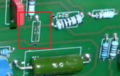
It has proven to be a good decision, because my older high power amplifiers (2 x 200W/4R, 2x330R/4R) used 30A relays as protective devices, and these relays have been the only parts that deteriorated during about 10 years of frequent operation. In 2017-18, I have switched the protective devices to SSR MOSFET relays, as can be seen in the photo. Same size of the small protecting boards, so they could have been replaced without the necessary repair of the amplifier main board. The main PCB (as posted in #1) was designed in 2016 taking into account the probability failure of the protecting mechanical relay, so it does not have them included in the main board. Same approach was used with the PA4 2x330W/4R amplifier.
It has proven to be a good decision, because my older high power amplifiers (2 x 200W/4R, 2x330R/4R) used 30A relays as protective devices, and these relays have been the only parts that deteriorated during about 10 years of frequent operation. In 2017-18, I have switched the protective devices to SSR MOSFET relays, as can be seen in the photo. Same size of the small protecting boards, so they could have been replaced without the necessary repair of the amplifier main board. The main PCB (as posted in #1) was designed in 2016 taking into account the probability failure of the protecting mechanical relay, so it does not have them included in the main board. Same approach was used with the PA4 2x330W/4R amplifier.
The pole is at 20KHz. The distortion does not increase as rapidly with frequency compared to amplifiers with a low-frequency pole.Looking at the compensation, I see no miller, tmc or tpc.
I do see the rc-network R27/R28 and the caps C14/C16 that goes with them.
Ed
Looking at the compensation, I see no miller, tmc or tpc.
I do see the rc-network R27/R28 and the caps C14/C16 that goes with them.
I am wondering about C1 and C2. I've seen this before, but haven't quite understood how this works. Assuming the PSU is low impedance, would it not be the same if they where connected to gnd then?
It is a CFA and thus compensation circuits are not automatically same as for VFA amplifiers. It is the transimpedance that is important and also value of the feedback resistor (R35//R24; 1k)) that creates a natural pole, please read documents at links in post #1.
simulated transimpedance

simulated loopgain with capacitive load up to 47nF

These are simulations only, so only informative value. For high capacitive load, I suggested to use 1uH//6R8 behind the amp output terminals.

I am wondering about C1 and C2. I've seen this before, but haven't quite understood how this works.
Please see effect of C1 and C2 on amplifier stability:
PMA, is it safe to use Toshiba 5200/1943? And I have 2SA1837 / 2SC4793 for drivers. Same BCE pin outs
I am sorry, but I cannot approve component changes that were not verified in a real circuit.
I may try to simulate, but again, the decision made from simulation cannot be a final approval.
I may try to simulate, but again, the decision made from simulation cannot be a final approval.
- Home
- Amplifiers
- Solid State
- PMA CFA - current feedback power amplifier with +/-25V to +/-55V dc supply range