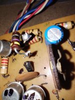
The left ones color code says 270k, I think?. Both resistors seem fine.this is what i get

I truly don't know, others may.i wanted to get one led lifted but this broke it looks like two diodes and one resistor on top i am wrong ?
The resitor should be 47 ohm.
Yes, the second band is probaly violet. Let's say he's OK.The left ones color code says 270k, I think?
Testing a component out of circuit requires desoldering it. Desoldering components from PCB that are not damaged can pull the lands off the boards. It can also break leads off the component. I've done both. The forwards-backwards diode test on b-e and b-c can determine some of which ones are bad quickly. sg97 has already determined both 2n3055 are bad. Likely one or both driver transistors are too. Those tests are to be done.There's one piece of test kit I'd strongly recommend to any newcomer, a cheap Chinese-made component tester - I'll add a photo of one below. It should cost around €20. I use mine all the time, probably even more than my multimeter. The real beauty is that you don't need to know what a component is, which way round the pins go, whether a transistor is NPN or PNP - the tester will tell you all of that.
After the absolute trash is gone, powering up through a light bulb, one can measure Vce on the transistors to determine which other ones are bad. <1 volt is bad. B-E <.6 volts is bad. Or find bad resistors, or find bad solder joints. This pcb has apparently been soldered by an amateur, which can cause bad solder joints.
here are transistors measured i think the right way if you guys can confirm that they are both gone then i have to find new ones.
From the clip I'd say they are good. What you think Indianajo?sg97 has already determined both 2n3055 are bad
So, both 270k and 120k are good.
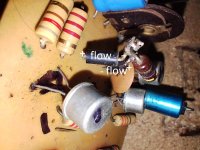
We need to focus on the ones with wire.
I would just assume they are the emitter resistors from the big transistors and replace them with 0.47 Ohm.
What is beneath the 47 ohm needs to be found.
Hugo
they measure in diode mode and not in resistance so they are two reversed diodes i am not sure why is that there resistor on top 46ohm measures ok
That's how they should be measured. Good.they measure in diode mode
46 Ohm is indeed OK.
Now to find out what's beneath them.
Hugo
Have a good look at both of them. Do they look like this?
There should be a grey band at one side. Which side on both parts?

There should be a grey band at one side. Which side on both parts?
they dont have any markings but i measure that one goes one way and second one in reverse so i can post a picture of polarity
We don't have a schematic but yes, you can be sure they need to be there.
I forgot, are the small transistors OK?
I forgot, are the small transistors OK?
i saved those for end xdd i will remove and measure them now btw i measured first one and it says 23 on hfe tester
Probably good, that 23, but measure them the same way you did with the big ones.
A small movie is always nice to follow.
I believe you have four of them. Take you time and make sure you remember where they were fitted.
Hugo
A small movie is always nice to follow.
I believe you have four of them. Take you time and make sure you remember where they were fitted.
Hugo
- Home
- Amplifiers
- Solid State
- transistor amp not working after shorting output