Well, I'm sure you will try it at some point. It will be difficult to go back, so I only hope you'll give me the credit 😉
I've finally unified the R-OSSE Desmos example at my website with the PDF documentation: https://www.desmos.com/calculator/66ve0qcwzcHere is a 3D visualization of a R-OSSE curve:
- https://www.desmos.com/3d/970a1eea44
Mmmh, it's already done and on my website in tweeter section, I speak about phase plug and it's well documented since century , like in compression driver you see ?
It was invented by German industrialist Werner von Siemens in 1877 then apply in audio around 1925 (General Electric engineers Chester W. Rice and Edward W. Kellogg) 😉
But I'm sure you will use it better by transform a plane wave front in a spherical wave front if I understood well, I hope you will have good results, of course I will give you credit if I use it, I'm honest, but I also hope you will not take credit of my regular phase plug for tweeter 😉
Don't be afraid, try it. It's almost a free lunch.

Last edited:
I have another 3D graph that morphs the y-part of R-OSSE by angle and distance:
- https://www.desmos.com/3d/e44c49f091
- https://www.desmos.com/3d/e44c49f091
That's exactly the kind of thing you can do with a parametric expression like R-OSSE right away (admirable work!). Try it with Bezier curves...
...I'm still working on the smaller EXAR. It uses an in-driver plug so it needs to be done a bit differently to accomodate various drivers in an easy way.
I already have several versions, this is another one. (The extension part makes obviously a good place to hold the whole thing.)


I already have several versions, this is another one. (The extension part makes obviously a good place to hold the whole thing.)
Last edited:
No, you didn't say that. You only commented on someting you knew nothing about.
I'm surprised how stubborn you can be sometimes ! 🙂. Okay, have it your way, keep your research, you're doing it well. I'm out.
I only wish people wrote only about what they actually know something about. Call me stubborn.
Does anyone have a photo of the exit of the ROSSO-65CDN-T compression driver?
It looks like a nice driver, I only wonder how well it is suited for usage directly from the phase plug exit...
It looks like a nice driver, I only wonder how well it is suited for usage directly from the phase plug exit...
Last edited:
Thanks, @tmuikku. So this simulated box here: https://www.diyaudio.com/community/...708-ish-dimensioned-2-way.377634/post-7469826, I had also simulated with 'proper' round edges.
Do you have the ABEC polar contour plots, horizontal vs vertical? The DI/ERDI doesn't show waistbanding but maybe you saw it in horizontal polars.
The style that looks like this
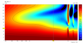
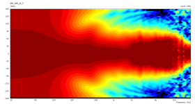
Yes, but only +/-180, so it's harder to see the 6 dB difference. The dip which results from the baffle is always 6 dB. The more shallow the enclosure depth, the lower its Q, and it becomes wider and also smoother.
This is my saved results from VACS, 1 dB increments, -30 to 0 dB range:
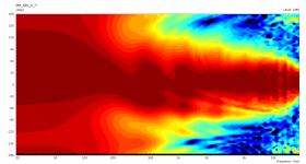
This is the view from FRD data in VituixCAD (on-axis normalized, 30 dB range, 2 dB contour line increments):
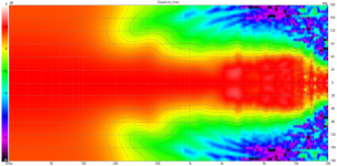
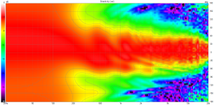
I must correct my previous statement: with a true roundover, the dispersion is much smoother (not shown). The strong ripples a result from using only a beveled baffle edge. However, this does not solve the narrowing in the midrange.
This is my saved results from VACS, 1 dB increments, -30 to 0 dB range:


This is the view from FRD data in VituixCAD (on-axis normalized, 30 dB range, 2 dB contour line increments):


I must correct my previous statement: with a true roundover, the dispersion is much smoother (not shown). The strong ripples a result from using only a beveled baffle edge. However, this does not solve the narrowing in the midrange.
Just as a side note - I guess developing something like ATH would not be possible without some stubbornness...Call me stubborn.
😊
@sheeple
You can add a line along the -6dB then export in VACS like this
1) Add the -6dB line in "Projection"; right click whole cursor is over the polar contour square
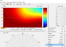
2) Change that box to -6 (the other two boxes are also useful for showing you 60 deg and where your potential crossover frequency)
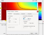
3) Export the image like you normally do
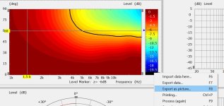
4) I like to click all the options then drag the image larger to make it easier to see, however, "Legends" is the one that shows your -6dB trace
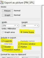
You can add a line along the -6dB then export in VACS like this
1) Add the -6dB line in "Projection"; right click whole cursor is over the polar contour square

2) Change that box to -6 (the other two boxes are also useful for showing you 60 deg and where your potential crossover frequency)

3) Export the image like you normally do

4) I like to click all the options then drag the image larger to make it easier to see, however, "Legends" is the one that shows your -6dB trace

The output is from some months ago and I did not want to re-run the full box sim now. I often use the marker option.
@sheeple ok, I can see it well enough using your original simulation. I'll describe how I'd approach it (For other members who know more than me, please interject and correct so I don't lead sheeple astray).
It looks like your overall enclosure size gives you control between 400Hz and 2kHz.
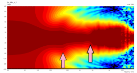
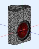
I'm designing a much smaller 2-way right now using a B&C 4NDSF34 with a narrower coverage angle waveguide. I included the ATH config file for you. You can measure the woofer diaphragm you have in mind for your project and shape it similar to the way I shaped the Source.Contour section. This enclosure simulates pretty fast because it's small so you can use it to get an idea of how you can shape your enclosure to match your waveguide instead of waiting on a large size enclosure to solve.
Personally - again, feel free to correct me if my approach is a bad idea - I do NOT match the waveguide to the woofer. Instead, I match the ENCLOSURE to the WAVEGUIDE. So the first thing I'd do is look at the pink arrow at 2kHz in your polars and try to use my enclosure to push my polars up (widen + flatten) to match your waveguide. Example #1 is the enclosure I'm currently using to match a waveguide for my project. If I wanted to start adapting my enclosure to your waveguide I'd begin making the first chamfer a lot more shallow and widening the overall enclosure. I only did it a little bit in my example so you could see how it moves the black -6dB line: flatter + wider above and below 2K. I didn't modify the tail on the enclosure. That's just a finisher that helps me deal with that bump where the enclosure loses control (i.e. the pink arrow around 400Hz in your polar contour plot). In your case, you'd want to keep widening your -6dB. You'd keep making your enclosure wider overall than my example #2. Further, because it's a single enclosure two-way you want to keep and eye on how your horizontal adjustments affect your vertical polar contour. Balancing H vs V is more difficult with both sources in a single enclosure than a freestanding horn + separate enclosure for the woofer. Both example 1 & 2 enclosures are included in the ATH config file. Just remove the underscore "_" from in front of "box" for the enclosure you want to simulate. I suspect your waveguide design will move your enclosure toward the Grimm Audio and GGNTKT style of enclosures. I've never tried anything that wide so I'm not certain. Except maybe not as flat across the baffle as those two speakers. You'll probably have some sort of shallow + wide first chamfer out to your enclosure sides. Also, you can add as many sides and turns as you want. Mine is just an example to show you how to adjust your first chamfer away from the baffle face to move toward matching the coverage angle and DI slope of your waveguide.
Example 1: Horizontal / Vertical
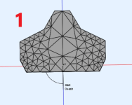
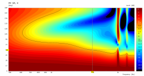
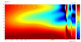
Example 2: Horizontal / Vertical
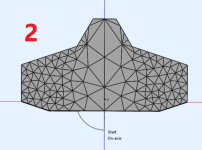
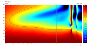
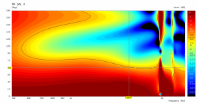
It looks like your overall enclosure size gives you control between 400Hz and 2kHz.

I'm designing a much smaller 2-way right now using a B&C 4NDSF34 with a narrower coverage angle waveguide. I included the ATH config file for you. You can measure the woofer diaphragm you have in mind for your project and shape it similar to the way I shaped the Source.Contour section. This enclosure simulates pretty fast because it's small so you can use it to get an idea of how you can shape your enclosure to match your waveguide instead of waiting on a large size enclosure to solve.

Personally - again, feel free to correct me if my approach is a bad idea - I do NOT match the waveguide to the woofer. Instead, I match the ENCLOSURE to the WAVEGUIDE. So the first thing I'd do is look at the pink arrow at 2kHz in your polars and try to use my enclosure to push my polars up (widen + flatten) to match your waveguide. Example #1 is the enclosure I'm currently using to match a waveguide for my project. If I wanted to start adapting my enclosure to your waveguide I'd begin making the first chamfer a lot more shallow and widening the overall enclosure. I only did it a little bit in my example so you could see how it moves the black -6dB line: flatter + wider above and below 2K. I didn't modify the tail on the enclosure. That's just a finisher that helps me deal with that bump where the enclosure loses control (i.e. the pink arrow around 400Hz in your polar contour plot). In your case, you'd want to keep widening your -6dB. You'd keep making your enclosure wider overall than my example #2. Further, because it's a single enclosure two-way you want to keep and eye on how your horizontal adjustments affect your vertical polar contour. Balancing H vs V is more difficult with both sources in a single enclosure than a freestanding horn + separate enclosure for the woofer. Both example 1 & 2 enclosures are included in the ATH config file. Just remove the underscore "_" from in front of "box" for the enclosure you want to simulate. I suspect your waveguide design will move your enclosure toward the Grimm Audio and GGNTKT style of enclosures. I've never tried anything that wide so I'm not certain. Except maybe not as flat across the baffle as those two speakers. You'll probably have some sort of shallow + wide first chamfer out to your enclosure sides. Also, you can add as many sides and turns as you want. Mine is just an example to show you how to adjust your first chamfer away from the baffle face to move toward matching the coverage angle and DI slope of your waveguide.
Example 1: Horizontal / Vertical


Example 2: Horizontal / Vertical


Attachments
I have this driver. Here is a photoDoes anyone have a photo of the exit of the ROSSO-65CDN-T compression driver?
It looks like a nice driver, I only wonder how well it is suited for usage directly from the phase plug exit...
But I dont know how much value this photo will be because I haven't yet been able to tear off that black damping material from top and remove the bug screen without damaging the whole black thing.. It is glued in such a way..
Thank you very much, Vineeth.
It's good news, so it can be used more or less as a 1" driver in an extended waveguide. 👍
(Even if a segment of a straight duct was to be inserted into the driver.)
It's good news, so it can be used more or less as a 1" driver in an extended waveguide. 👍
(Even if a segment of a straight duct was to be inserted into the driver.)
- Home
- Loudspeakers
- Multi-Way
- Acoustic Horn Design – The Easy Way (Ath4)