
Lorlin Alignment Nub
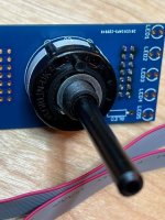
I'm a bit confused about the Lorlin Switch Twister alignment. The PCB silkscreen notes the the alignment nub should be on crosshares of C6. Or in the 6 oclock postion, I assumed the alignment nub is what fits in the hole in the face plate of chassis. The chassis faceplate hole is at 12 oclock. I can't find well lit pic to guide me. From what I can tell from the pcb schematic might not make a difference for the SE.
Could the alignment nub be the white half moon bump opposite of the black plastic nub to hold switch in place.
Attachments
I placed mine as your first photo shows and it is working fine. I have an SE model, but I doubt that it matters.
Lorlin Alignment Nub
irrelevant
whichever of 2 possible orientations is fine
so either "this way" or "180deg rotated" , just chill
Thanks! I think I will rotate the switch 180 deg so that the nub will be in the 12 oclock position and fit in the hole in the face plate. That way the leds will fit in the pcb and faceplate. The first photo above puts the leds on the wrong side and wont fit in the faceplate. Will ignore the C6 crosshair part of the build guide.
No matter how much I train I seem incapable of this thing you call "chill" 🤔
No matter how much I train I seem incapable of this thing you call "chill" 🤔
Switch will work... yes...irrelevant
whichever of 2 possible orientations is fine
so either "this way" or "180deg rotated" , just chill
But... have you considered that the "nub" fits into a hole on the chassis... and that the LEDs also have to be to one particular side... to fit into their holes...
Reason I put special note in build guide. 🙂

Edited to add - For boyz and girlz doing their own chassis stuff... yeah... no worry at all, agreed.

"Save the Nubs!"
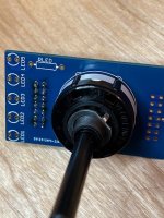
I had it on top initially as it seemed that was the logical choice to get the leds on the right side. I changed it after I read the build guide portion that says,"Be sure to align the nub on the switch to the crosshairs on the PCB above the marking C6." That unfortunately puts the nub on the bottom and wont fit in the faceplate. Rotating the PCB to get the nub on top then puts the leds on the wrong side. And shortly thereafter my brain started to melt.
I had it on top initially as it seemed that was the logical choice to get the leds on the right side. I changed it after I read the build guide portion that says,"Be sure to align the nub on the switch to the crosshairs on the PCB above the marking C6." That unfortunately puts the nub on the bottom and wont fit in the faceplate. Rotating the PCB to get the nub on top then puts the leds on the wrong side. And shortly thereafter my brain started to melt.
^ I have not seen the chassis in person... but I just checked the chassis rendering against a Lorlin switch and the twister board.
You are correct! Leave yours as is, of course. I need to check with mighty 6L6 to see how he got his to fit into the front panel properly. When I look at the middle photo in Step 14, it shows the "nub" on the bottom with the switch in that orientation. The rendering I have for the chassis shows the nub on the "top"...
Mainly... very happy that your brain didn't melt and that it fits properly. You did it properly.
More to come...and thank you for pointing it out!
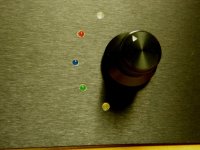

1mm hole is perfect for any led behind it
This is very good advice. I found out the hard wat that a 5mm LED can be very annoying while listening to music, and of course blue in the Pass tradition makes it worse than say a red LED. I had to dim it a lot with, I don't know how many kiloOhms resistance. 😳
These are 3mm LEDS and I have decided to use bezels for them. I have a larger resistor that works well for them.
ZM's Thumb of Rule - 1K per rail Volt
don't know how many kiloOhms resistance.
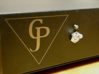
For many moons I've used these or a different colour. The long 'snout' was perfect for holding it in place if you drilled the correctly-sized hole(s) and the flat top could then be aligned flush with the face of the front panel. Looked sexy. Unfortunately Panasonic has discontinued them but there are a few substitutes in limited colours. A few years back I shelled out on a dozen or so 4-pin 2mm RGB versions in the same style and they served well to multitask - normal was blue or green, mute was a blinking blue, a trouble condition or standby was red etc - but the company i got them from - think it was LEDSales - hasn't stocked them in a while. A quick look did find these though.
And, of course, His Mightiness is Omnicorrect - smaller the hole nicer the effect 🙂.
And, of course, His Mightiness is Omnicorrect - smaller the hole nicer the effect 🙂.
Last edited:
just for giggles, next time** twist your signal wire pairs and triples
if nothing else, it looks neater
**every proper DIY house needs to have multiple Iron Pre
Advice taken and thank you ZM for your many generous offerings!
- Home
- Amplifiers
- Pass Labs
- Iron Pre Essentials Kits For The DIYA Store - Register Your Interest