II use those too in circuits. Mostly power supplies.The Dale CMF series does have a nonmagnetic lead option.
Vishay bought Dale who purchased Chicago Resistor and Mills So there are a few shared designs shared across brands.
That is why you will see MRA series listed as Vishay/Mills in some parts stores online.
Now you understand why a grid stop resistor is important especially in certain tube circuits.Here's the horse's mouth, Miller himself, in 1919 discussing instability in the grid circuit.
The added external grid impedance should make the total input impedance positive.
Here's the horse's mouth, Miller himself, in 1919 discussing instability in the grid circuit.
The added external grid impedance should make the total input impedance positive.
The late DF96 once wrote that in his experience, inductance of grid stopper resistors doesn't matter much. It took me a while to understand that that was perfectly logical as long as the resistance of the grid stopper was greater than the absolute value of the negative resistance seen at the grid. By the time I finally put two and two together, DF96 was no longer with us, so I never had a chance to write this to him.
Regarding thermal noise, the only things that matter are resistance and temperature - a resistor with a temperature of 313 degrees Celsius will produce about 3 dB more noise than one at 20 degrees Celsius.
Resistor 1/f-noise manifests itself as small random resistance fluctuations. As long as there is practically no current flowing through the resistor, you shouldn't notice it.
All in all, at least in theory, just about any small-size resistor that you can place close to the grid should do the trick.

Experience with VHF oscillators shows you don't need much resistance on the grid in-fact 100R was sufficient to kill the oscillator with an ECC88.
I doubt some residual inductance in most resistors should be a problem. Inductance will increase the impedance at high frequency, which should be a benefit. But also add some sort of series RLC resonance, together with the Miller's stage capacitance.
I see residual resistor capacitance as more of a problem, because it will bypass the resistance value and couple high frequencies. From that POV, I wouldn't use wirewound non-inductive resistors.
However without any real-world values, it isn't worth it to draw any conclusions.
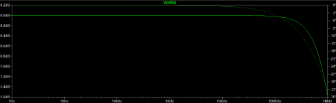
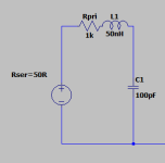
Here is a frequency response simulated with and RLC, 50R driving impedance, 1k resistor value, 50nH parasitic inductance added, 100pF shunting capacitance.


Here is a frequency response with 100pF parasitic capacitance across the resistor


I see residual resistor capacitance as more of a problem, because it will bypass the resistance value and couple high frequencies. From that POV, I wouldn't use wirewound non-inductive resistors.
However without any real-world values, it isn't worth it to draw any conclusions.
Here is a frequency response simulated with and RLC, 50R driving impedance, 1k resistor value, 50nH parasitic inductance added, 100pF shunting capacitance.
Here is a frequency response with 100pF parasitic capacitance across the resistor
Attachments
I think you need to buy a mills MRA5 resistor the size of one of the cathode resistors in a line amp and hear the difference. I like how it cleans up the tube noise when looking at the plate on the scope.I doubt some residual inductance in most resistors should be a problem. Inductance will increase the impedance at high frequency, which should be a benefit. But also add some sort of series RLC resonance, together with the Miller's stage capacitance.
I see residual resistor capacitance as more of a problem, because it will bypass the resistance value and couple high frequencies. From that POV, I wouldn't use wirewound non-inductive resistors.
However without any real-world values, it isn't worth it to draw any conclusions.
Here is a frequency response simulated with and RLC, 50R driving impedance, 1k resistor value, 50nH parasitic inductance added, 100pF shunting capacitance.
I'm not sure how those model values scale, but they seem too large. 100pF would be difficult to achieve even if desired, and plain wire is what? 1nH/mm or some other tiny number. If that's off by several orders of magnitude, doesn't matter. A bulk resistor can have negligible parasitic Z's for this gig. But it does need to still be a resistor at somewhere around the top of the HF band, maybe 30MHz.
But your point is taken; a lossy inductor also does the job.
Thanks, and all good fortune,
Chris
But your point is taken; a lossy inductor also does the job.
Thanks, and all good fortune,
Chris
I think you need to buy a mills MRA5 resistor the size of one of the cathode resistors in a line amp and hear the difference. I like how it cleans up the tube noise when looking at the plate on the scope.
We need to dig up a bit on cause and effect, instead of wild guessing. If there is noise, what causes it. Is it the resistor? Besides, we're discussing grid-stopping capabilities, not noise, which is for another topic.
Chris, yes, 100pF seems impossible from my POV as well, but I oversized the value as a worst-case estimate.
yes. Most of the time, you oversize to overcome coupling issues.Experience with VHF oscillators shows you don't need much resistance on the grid in-fact 100R was sufficient to kill the oscillator with an ECC88.
I know the cause and effect. You guys don't know me that's all.We need to dig up a bit on cause and effect, instead of wild guessing. If there is noise, what causes it. Is it the resistor? Besides, we're discussing grid-stopping capabilities, not noise, which is for another topic.
Can you elaborate neutrally to a point, instead of mixing up personal feelings within the discussion? If we don't know you, no one keeps you from sharing.
Yes the lossy inductor is fine. In terms of oscillation in VHF your more likely to see this with a cathode follower. 1K will stop this CC or metal film. As for noise figure on a 12ax7 gain stage your looking at tens of Kohms before the resistor noise figure will have an effect.
The noise contribution of any kind of resistor, used as a grid stop, is just its Johnson/Nyquist/thermal noise, irrespective of brand or religion. No significant current passes through it, so it doesn't contribute excess noise, and it operates at ambient temperature. This is an area where audiophoolery has gotten ahead of the curve, but certainly not the first.
All good fortune,
Chris
All good fortune,
Chris
Just googling lots on religion and resistors but not for this forum.
I need to take a pause for a moment. I just found out that Dave (DF96) passed away. I'm sorry.Can you elaborate neutrally to a point, instead of mixing up personal feelings within the discussion? If we don't know you, no one keeps you from sharing.
The noise contribution of any kind of resistor, used as a grid stop, is just its Johnson/Nyquist/thermal noise, irrespective of brand or religion. No significant current passes through it, so it doesn't contribute excess noise, and it operates at ambient temperature. This is an area where audiophoolery has gotten ahead of the curve, but certainly not the first.
All good fortune,
Chris
I have slightly different arguments towards such "quickshot" claims. If one measures an effect, in this case noise, the culprit might not be necessarily be the resistor itself. I still find it hard to believe how quickly people jump to final conclusions and claims.
Tube like anything else can be modelled including noise figures. There's a few papers and they do make interesting reading:
https://tavishdesign.com/pages/audio-tube-noise-measurments
If you want very low noise then
https://en.wikipedia.org/wiki/Nuvistor
https://tavishdesign.com/pages/audio-tube-noise-measurments
If you want very low noise then
https://en.wikipedia.org/wiki/Nuvistor
As for noise figure on a 12ax7 gain stage your looking at tens of Kohms before the resistor noise figure will have an effect.
Actually, the noise performance of the 12AX7/ECC83 is remarkably good according to @Merlinb 's measurements. RIAA- and A-weighted noise of the order of 5 nV/√Hz when optimally biased, if I remember well.
Much noise significant in audio falls into the category of "excess noise", defined as anything in "excess" of the fundamental, linear, predictable and calculable, ideal model of perfect devices. Included in the ideal model are thermal/Johnson/Nyquist noise (RT) and the noises of current crossing junctions. Anything in excess of these ideals are "excess".
Unfortunately, excess noises are deep voudou, process-specific, and not calculable (only guarantee-able through testing). For a really scary look at the limitations of current understanding, try to understand 1/f noise. It's everywhere in the universe, and at hugely varying scales, and nobody has yet got much understanding - great project for a young scientist.
This is pertinent to audio because 1/f noise becomes significant esp. in RIAA amplifiers, and is often a limitation on the use of RF oriented valves, which might easily have very high 1/f knees. Another example would be MOSFETs.
All good fortune,
Chris
- Home
- Amplifiers
- Tubes / Valves
- Does audiophile tube builders know what a grid stop is for?