as of now, we have no Aegis transformer sets on hand, sold out, but you can of course order a set, which right now, would be shipped by mid to end of November.
We should also have 'stock' sets back by mid to end of November.
We should also have 'stock' sets back by mid to end of November.
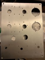
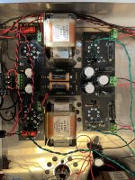
What do you guys think of this layout? I was going to mount the power and output iron on top but there seems to be ample room in this chassis.

looks good, but I would still 'shield' the power transformer, maybe a sheet of aluminum between the power transformer and OPT.
Did you make the chassis yourself, if not, where did you get it from.
Did you make the chassis yourself, if not, where did you get it from.
I'll mount the power up top then. Your can hit up my buddy Horace at http://www.iagaudio.com ... he does amazing work and is very reasonable.

sounds good. If you need a Lundahl transformer enclosure for the larger power transformer, drop me a 'pm'
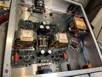
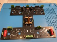
I built my Aegis but it doesn't work very well. There is noise (hum) in the left channel.
It is not from DAC (disconnected) or tubes (I swapped all 5 of them).
Can anyone suggest what to do?
Maybe I should build another PCB and try that. Is it going to help?
I tried changing some wires (from IEC inlet) , resoldered heater wires and some resistors. Absolutely nothing changed.
It is not from DAC (disconnected) or tubes (I swapped all 5 of them).
Can anyone suggest what to do?
Maybe I should build another PCB and try that. Is it going to help?
I tried changing some wires (from IEC inlet) , resoldered heater wires and some resistors. Absolutely nothing changed.
Attachments

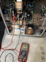
Perhaps first try to flatten the wires as much as possible, so that they do not capture the various radiations from the starter and the power wires.
then try to separate the signal wires and the power supply wires as much as possible.
then try to separate the signal wires and the power supply wires as much as possible.
FYI, Dave at Landfall requested a change to the bottom venting for Aegis with the below configuration. Functionally the same but less taxing and more time efficient in terms of machining. I said it was fine, so orders going forward would have this venting pattern.

Great and beautiful chassis btw, looking as if it bought from an high end firm. Very recommended if you cannot build your own. Dave is a pleasure to deal with.
Already built 3 Aegis and absolutely no noise, nothing. The layout is perfect. Did you tried inverting the tubes, did the problem stayed on the same side? Also compared the DC readings on the pcb, from side to side. The should be the same.
No offense MarisO but your internal wirings can be tidier. Not at home presently, will send a picture of mine tomorrow.
Will send also my own voltages readings for you to compare.
SB
Last edited:
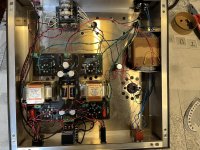
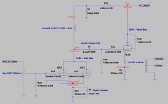
Here my own assembly, and my own amp voltages readings. Take note that around here line AC voltage is 120V, and may be 115V where you live, meaning you'll have lower HV readings, since the power supply is a simple tube rectifier without any regulation. Also my volt readings were taken using EL34 power tubes.
SB
SB
Attachments
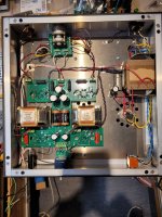
Look at post #113. Excellent execution. Main sins appear to be disorganized wiring, much of it too long. Be especially careful with AC (mains) wiring which appears to be running wild throughout the board, very likely inducing hum.sure
Everything is in the doc. I should have read the doc more closely instead of skimming 😅How do I get a kit?
I only just created this account and can’t message people.
@L0rdGwyn Since you are the engineer and I am nobody.. LOL. I am considering building the amp in two (2) sections. Bottom contains AC-in, transformers, rectifier and chokes - divided by sheet metal - then top floor contains tubes and the electronics. So smaller footprint but taller chassis.
If the general rule as outlined in the PDF and other common sense approaches are applied, do you envision any problems ?
If the general rule as outlined in the PDF and other common sense approaches are applied, do you envision any problems ?
@Oneminde no I don't think there would be any issues if the layout is sound. If you're going to do a two-level design you might consider putting the power supply circuitry on one level and the signal circuitry on the other to minimize the noise floor. So mains transformer, rectifier, power supply choke and reservoir capacitor on one level, and the remaining circuitry including the anode chokes and the output transformers on the other. This will keep high voltage alternating current and ripple currents away from signal circuitry.
Also, I'm not an engineer 😉
Also, I'm not an engineer 😉
I was thinking OP-trannies could be mounted in the bottom chassis and section it such that AC/DC and mains is shielded from the OP-trannies. Essentially blocking off power, electronics and OPT from one another and in two levels.
And thanks for "approving". I have the manual plus Morgan Jones books on tube amp building. I'll start working and planing out how things will look. I will ofc share my progress in steps and run them by the forum in case something becomes a problem.
Many thanks 🙂
And thanks for "approving". I have the manual plus Morgan Jones books on tube amp building. I'll start working and planing out how things will look. I will ofc share my progress in steps and run them by the forum in case something becomes a problem.
Many thanks 🙂
- Home
- Amplifiers
- Tubes / Valves
- Aegis DIY Tube Headphone Amplifier