A square wave can be thought of as the sum of a sequence harmonically related sine waves with set amplitudes. An ideal square wave requires an infinite sequence of harmonics. In the real world changes in amplitude of the harmonics diverge the shape of the wave from square.What makes the wave curve like that? Pretend I didn't study engineering.
Attachments
Best scope I've ever owned 🤔
Do you have proper attenuator probes?

Hi Rayma, It is a 200kHz scope, so even with a proper probe (they do come with one) it will be challenged to display a near perfect 10kHz square wave. I asked for one of these scopes for Christmas because it looks like fun to put together. They cost literally nothing. 🙂Do you have proper attenuator probes?
Show us what it looks like with probe connected to signal generator, i.e. no amp involved...
//
//
Hi Rayma, It is a 200kHz scope, so even with a proper probe (they do come with one) it will be challenged to display a near perfect 10kHz square wave. I asked for one of these scopes for Christmas because it looks like fun to put together. They cost literally nothing. 🙂
Right, but the scope can load the circuit unduly if connected directly, without a probe.
Watch out for what is being ordered, a lot of hits for that scope are only for the case or power supply, not the actual scope.
Even if there's a photo of the scope itself.
A bandwidth of 200kHz should give a decent 10kHz square wave, with 20 harmonics.
Last edited:
Show us what it looks like with probe connected to signal generator, i.e. no amp involved...
//
Something around 10-20k straight from the gen to the scope. Hard to tell exact freq coz it's just a knob. Range is 3-65k.
The generator or the scope can't keep up in the 65k+ range. This shot is the top end before the square gives away to a shark fin:
https://www.amazon.com/Oscilloscope-Handheld-Soldered-Electronic-Learning/dp/B08DJ1YS99I know, but it's really hard to tell what you're ordering.
In the ad there's a picture of the scope, but buried somewhere in the text is "only the case".
It probably is better than the Heathkit single channel recurrent sweep IO-102 I assembled way back.
https://www.amazon.com/Oscilloscope-Handheld-Soldered-Electronic-Learning/dp/B07X2MQFJ2?th=1
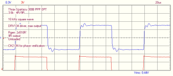
1Khz square wave test for a tube poweramp is ok because the result can be used for analysis. 10Khz square wave seems to be an invalid test, especially for the SE amp.
The combination of the 6SL7 gain, Miller Effect Capacitance, and 250k Pot might be part of the upper frequency limit.
If you turn the 250k pot to mid resistance, 125k, (not mid rotation), you will get a slower rise time than if you use a low impedance generator and turn the pot all the way up.
Test to see if the 10kHz signal rise time changes when you trade off the generator output voltage versus the pot setting (the combinations that are set to the same amplifier voltage output). If it changes, that means when you listen to a CD, and change the volume setting for a loud CD and a quiet CD, the high frequency response will change.
I use low impedance signal sources and low impedance signal generators, and a 50k Pot to keep the Miller Effect Capacitance from significantly rolling off the high frequencies.
That 10kHz square wave looks like a nice gaussian filter effect.
I bet that with the 250k pot set to 125k, the Miller Effect Capacitance causes more high frequency loss in the 6SL7 input; Versus the Miller Effect Capacitance of the 6B4G.
( because of lots of voltage gain in the 6SL7, versus low voltage gain in the 300B).
Happy Listening!
Last edited:
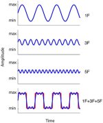
It may be helpful to understand that a square wave is build up of a sinewave at the fundamental frequency, plus a sinewave at 3 x fundamental frequency, plus sinewave at 5 x fundamanetal frequency etc.
For the square wave to be really square, these sinewaves need to be in a precise level.
The 3rd needs to be 1/3 the fundamental, the 5th at 1/5 the fundamental, etc.
Since all amplifiers are low pass filters, the 3rd, 5th etc components will be attenuated with respect to the fundamental, which gives the rounded edges.
So it is absolutely normal, in fact if it wasn't it could indicate a non-flat frequency response.
Jan
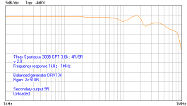
I'm attaching some square wave vs frequency response comparison, so that you get a hint of what is happening one vs the other.
Attachments
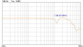

When you look at the square wave response directly from your generator, with nothing in between, as a normal basic check before doing all kinds of stuff, that should be flat and give a ripple-free response. I expect that not to be thecase.
Jan
Jan
- Home
- Amplifiers
- Tubes / Valves
- Help me understand? 10kHz square wave thru my SE amp