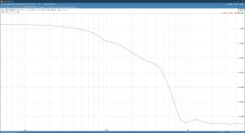
In the meantime you could check and post a picture of the 1KHz square wave response, and check the gain is not starting to go up at 1Hz.
Oh that was short an sweet.
They don't make 'm like they used to anymore!
In the meantime you could check and post a picture of the 1KHz square wave response, and check the gain is not starting to go up at 1Hz.
1Hz? I'm assuming you mean check for overshoot?
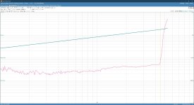
Just check you don't have a peak in gain at about 1Hz due LF instability. Just another thing to check on your tick box.
Give it a small step transient and look at settling. If it bounces a bit before setting out (LF ringing) it needs attention. Really not all that hard a fix, if needed.
As requested, 10W/8R, looks pretty good to me, but I'll see if further tweaking will give better results.

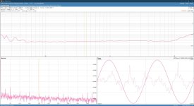
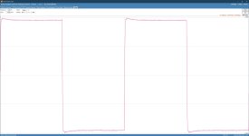
Not just simulation wise. Real circuit as in actual hardware. OPTs are notoriously hard to MODEL accurately. Behavior in the real amp with a 100 mV DC step (into its AC coupled input) is very telling. It can settle out quickly, ring, or even break into sustained sub-Hz oscillation. Just watch the scope trace and see what happens. That will tell you if it needs fixing.As requested, 10W/8R, looks pretty good to me, but I'll see if further tweaking will give better results.
View attachment 1233130
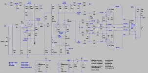
The JET on the Kicad schematic I sent you connected to the REF pin. The idea is that on startup the JFET is on. This pulls the REF to -.6V which causes the grids to go full negative. After about 15s the gate of the JFET is pulled to -10V or so. This allows REF to become .38V and the circuit acts in servo mode. This stops the grid voltage ramping up when the tubes are cold. Note don't put a C across R11.
Not just simulation wise. Real circuit as in actual hardware. OPTs are notoriously hard to MODEL accurately. Behavior in the real amp with a 100 mV DC step (into its AC coupled input) is very telling. It can settle out quickly, ring, or even break into sustained sub-Hz oscillation. Just watch the scope trace and see what happens. That will tell you if it needs fixing.
FYI, here's the proto I have running on the bench:
No need to be rude to folk on a friendly discussion forum. OPTs are only vaguely modelable at best, because many important variables are so level-sensitive. Measurements at a single signal level aren't, unfortunately, enough for a really believable OPT model at low frequencies. (It matters for feedback stability, see DTN Williamson). The map is not the world, and someone's measurements are also not the world. God and the Devil dwell together in the details, and both are subject to second party scrutiny.These are actual measurements on the prototype, pleae stick with the program!
All good fortune,
Chris
I'm sorry Chris, as although I appreciate feedback, I do expect people to familiarize themselves with the topic. In the last two pages I've made it abundantly clear I'm posting actual measurement plots, not simulated results. To answer the latter part of your reply; if you had taken a minute to look at these measurements you'd realize they're 1) not at a single signal level and 2) I'm not interested in modelling the OPT at this point, as I have a working prototype and thus that's my focus, I merely use the schematic capture option of LTspice to make adjustments to the schematic so I can share these in this thread. Thanks!
Probably my bad for ****uming that since a spice schematic was presented and the plots all digital generated by *computer that it was just a simulation. I’m VERY skeptical of claims based solely on simulation because there are just too many pitfalls.
Pretty PCB BTW. interesting way to do a 3 layer board.
Pretty PCB BTW. interesting way to do a 3 layer board.
That's alright, I didn't mean to snap at you. And I'm 100% with you on simulations usually being too optimistic. The proto is MDF board with 2 oz. copper tape and copper nails, I've been doing it this way for a good 30 years, works a treat and the copper tape makes for a very effective ground plane. This works better than P2P in my experience.
- Home
- Amplifiers
- Tubes / Valves
- KT88 PP - Dotting the Is, crossing the Ts