Hello,
We are on the road to nowhere ( Talking heads!)
Greetings,Eduard
So unwatch and read Canterbury tales instead
We are on the road to nowhere ( Talking heads!)
Greetings,Eduard
So unwatch and read Canterbury tales instead
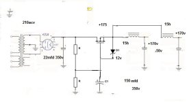
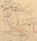
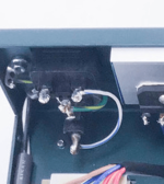
Updated schematic and new physical wiring diagram (actual size). My eyes are going boggly. 😵💫 I am sure there is something I have done wrong here. I still need to draw the XLR jacks in. I'm not sure I have the signal common points and chassis grounding proper.


Re the choke orientation test....
I am assuming you do this with Cossor choke and output transformer "out of circuit".
I tried it with the LP-900 connected primary to 110ACV and outputting about 7 VAC on the secondary.
Connected the secondary wires to "a" and "b" of the cossor.
Put a voltmeter set to ACV across the primary of the OPT....
moved it close beside the cossor....and nothing...no volts detected.
I am assuming the cossor induces voltage via the coils ? and you should be able to measure this on the primary of the OPT? I did not try yet with 120VAC instead of 6.3VAC.
Attachments


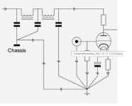
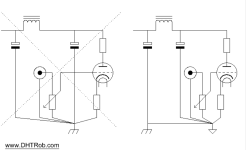
Hooman is showing how to set up a virtual center tap for your 5687 heater connections.
If you have a center tap on your heater transformer winding, this shouldn't be necessary.
If you don't have a center tap on your heater transformer winding, and you hook everything up, and it all works except you've got a very aggressive buzzing noise in the circuit, you may need a center tap.
I would use More than 47 Ohm for the resistors, personally--at least 200. They'll be in parallel, which will result in lower resistance. There's no need to be passing much current through them so higher resistance is better.
Sure, and connect the power transformer like this?? Everyone has left!What's your problem man? Let the guy learn.
I have always read and applied Earth goes directly to chassis as soon as it '' leaves '' the IEC connector with a short connection and officially the bolt used for that should NOT be used for any other connection.Look how the software has drawn Power AC input - Live/+ and Negative/- which is then connected to Earth/Chasis - maybe this is what trips the software - it should be drawn with 3 lines for AC : Live/+, Negative/- and separate Earth.
Live and Negative goes to Fuse + Switch ( one or both, depending on what You want and the type of the Switch ) and the third line : Earth goes straight to Chasis - this is if You are using IEC connector.
The original sockets i saw here had an isolated ceramic post to '''support'' the signal parts in an isolated manner but suddenly these parts no longer mounted that way. The correct procedure has been described in the link in post #235 and after that in numerous others epistles.
Attachments
Eduard please - i was commenting on software's representation of AC side / Power input from IEC connector ( Earth to Chasis )-Fuse- On/Off Switch, nothing else - nowhere did i comment on signal grounding.I have always read and applied Earth goes directly to chassis as soon as it '' leaves '' the IEC connector with a short connection and officially the bolt used for that should NOT be used for any other connection.
If this comment has done some mess i'm sorry for this.
aurieges-l is high end tube preamp.made in japan.ken shindo used 6x4 in power. please look at ground. Ken was one of the most skilled designers in the tube preamp and power amp . he used tow tube section in preamps.The first is amplification, and the second one is a cathode follower, without amplification effect, but excellent in correct reproduction of harmonics.Hello Belgrade,If this comment has done some mess i'm sorry for this.
Your info was correct so was the info in the link i provided but things are still being messed up in all kind of ways.
And in a way that things will not even work instead of working in a mediocre way which is a shame.
Especially the signal part of this device is very basic and the info given in the links and attachments is enough to start things going.
Output transformers being drawn the wrong way( phase dot) is not that bad if the actual execution is ok
But high voltage transformer being drawn with wall outlet connected to center tap of high voltage on secundairy side without any reason being given to do that in more than 250 posts is not right.
Maybe it was an idea from Morgan Jones book? I will check my copy.
Greetings Eduard
WARNING: Tube/Valve amplifiers use potentially LETHAL HIGH VOLTAGES.
Building, troubleshooting and testing of these amplifiers should only be
performed by someone who is thoroughly familiar with
the safety precautions around high voltages.
Building, troubleshooting and testing of these amplifiers should only be
performed by someone who is thoroughly familiar with
the safety precautions around high voltages.
Hi. I believe I fixed the IEC connector in the schematic of post 263?Eduard please - i was commenting on software's representation of AC side / Power input from IEC connector ( Earth to Chasis )-Fuse- On/Off Switch, nothing else - nowhere did i comment on signal grounding.
If this comment has done some mess i'm sorry for this.
This is obviously an error as the schematic doesn't show it like that, but thank you for pointing it out.But high voltage transformer being drawn with wall outlet connected to center tap of high voltage on secundairy side
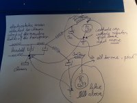
I do not understand where the ceramic posts are in that attached diagram 3 in post 269. Or how they are represented in that logical diagram. I see a ground common to all signal parts and the ground going to chassis ground, but this can't be the same one that the IEC protective ground is going to?? Even though "chassis is chassis"?The original sockets i saw here had an isolated ceramic post to '''support'' the signal parts in an isolated manner but suddenly these parts no longer mounted that way. The correct procedure has been described in the link in post #235 and after that in numerous others epistles.
Or how the ceramic post works with a single tube being used for both channels and how the ground works.
I placed a note beside my signal diagram that said how I planned to ground it. Obviously it isn't correct, but I don't understand how what I drew is different. All commons go to a ground point (ring around the socket which is screwed to chassis and tube socket is bolted to the metal ring). When using both sides of the tube, does left channel commons go to one of the points on the ring and right side channel commons go the another point on the ring? Are 2 ceramic posts used?
When I measured the two metal bars coming out of the ceramic they were both connected to each other. i.e. zero ohms between the bar on both sides of the ceramic and the ceramic bar thing attached to ground ring.
For sure. Exactly why I'm not hooking anything up until i understand how it works.WARNING: Tube/Valve amplifiers use potentially LETHAL HIGH VOLTAGES.
Building, troubleshooting and testing of these amplifiers should only be
performed by someone who is thoroughly familiar with
the safety precautions around high voltages.
Why did you remember this danger?هشدار: تقویت کننده های لوله/شیر از ولتاژهای بالقوه کشنده استفاده می کنند.
ساخت، عیب یابی و تست این تقویت کننده ها فقط باید باشد
توسط شخصی که کاملاً با آن آشنایی دارد انجام می شود
اقدامات احتیاطی در مورد ولتاژ بالا
Hello,Why did you remember this danger?
Shindo at least used a short connection but in my country ( all EU country i think) this wire must be connected to the chassis with a separate bol;ts that is ONLY used for this connection and not with the one of the bolts that is used to mount the IEC connector. People will say but it will work the same. BUT it is not according to regulations!
Both ways of wiring will give sound of one is better than the other.
I try to explain several times and posted the correct way a few times with no succes . But it is the same. No it is not the same.
Bye bye, Eduard
Attachments
- Home
- Amplifiers
- Tubes / Valves
- "Serious Pre" Tube Build