Hi everyone. I have updated placement of parts to closer match my block diagram. This hopefully achieves shorter wires where it’s important. And also locates parts like transformers and large resistors to act as shields or eliminate noise from windings.
.png")
Attachments
-
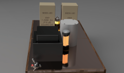 SeriousPre_2023-Oct-29_02-17-36AM-000_CustomizedView11408534864 (1).png154 KB · Views: 60
 -
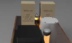 SeriousPre_2023-Oct-29_01-32-58AM-000_CustomizedView7326009670 (1).png209.3 KB · Views: 55
 -
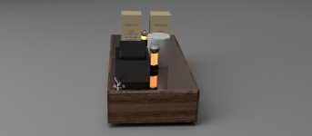 SeriousPre_2023-Oct-29_01-24-06AM-000_CustomizedView15768100129 (1).png97 KB · Views: 54
 -
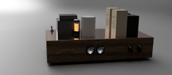 febce9e4-98fc-4d11-8dc2-aca245e25687 (1).png132.6 KB · Views: 60
The 5687 right in between all those components? Not that you'll be doing it a lot once you're done, but it sure looks like it will be awkward to remove and insert it.
The rectifier tube is also extremely close to the transformer.
Consider giving yourself a few centimeters around the tubes if possible.
Is this personal preference or because of an actual limitation? Saving yourself a few cm on wiring runs is not going to make a difference.
Not sure I've ever heard someone use transformers as "shields" as the kind that you are using (non-toroidal, non-R-core) are the things that tend to radiate EMI.

Good point. Maybe they are too close. That’s why I want to test placement on a board first.
Apparently the big metal housing on the Sic-safcos helps. And location of heater transformers being under the power transformer is what I meant. Those aren’t shields. Just putting the primary windings to the back side of the case I think.
Apparently the big metal housing on the Sic-safcos helps. And location of heater transformers being under the power transformer is what I meant. Those aren’t shields. Just putting the primary windings to the back side of the case I think.
Regarding picture - inside layout - where eill You put IEC connector ?
Looking down at the left where it would "normally" be You have ( looks like ) large and long capacitor.
Looking down at the left where it would "normally" be You have ( looks like ) large and long capacitor.
Yes. I’ve moved that cap to the proper place so power I put can go on back panel under switch.
I’ll put up another transparent view.
I’ll put up another transparent view.
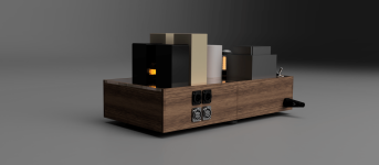
I see the logic to having the 5687 where it is. Personally I would move it closer to the PSU so it's the mid-point between the audio and power circuits. If you do that, you can minimize loop length / area from the PSU (B+ and heater wiring both) and completely segregate it from the interstage/output transformers.
As an example, the heater wiring with respect to signal wiring from the inputs. Does the heater wiring need to be brought directly under all the signal circuitry?
To me it looks like you have plenty of distance between the power supply and audio stage and won't need that center shielding barrier. I would add that to the things to consider when prototyping: do I really need it? From what I've seen, shielding (unless using mu-metal or entirely enclosing sources of EMI) is overrated. Wire routing, twisting, and grounding much more important, especially when you are dealing with such small currents.
Obviously you've got a lot of time on your hands so just more grist for the mill. You'll see what matters and how much when you prototype.
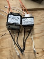
Thank you @Thekak. These are all good points. The heaters are two LP-450 and LP-900 transformers and the wires go from under the main power transformer where the heater transformers are bolted on a perf-board. One to heat the rectifier tube 6x5 and the other to heat the 5687 signal tube.
The larger heater transformer is for the signal tube (more amperage) and the smaller one is for the 6x5. I have to rotate them 90% from the model above as I am just looking at the physical parts now and the pins are at the ends of the longest dimension....
The larger heater transformer is for the signal tube (more amperage) and the smaller one is for the 6x5. I have to rotate them 90% from the model above as I am just looking at the physical parts now and the pins are at the ends of the longest dimension....
Signal LP12-450 test in parallel to see if I get 6.3VAC on secondary. I am getting 8VAC vs the 6.3VAC....
Black and White cloth 18awg is 120VAC is primary parallel tapped. 1,3 and 2,4
Orange and White plastic smaller wire is secondary parallel tapped. 5,7 and 6,8
https://www.mouser.ca/datasheet/2/643/ds-st-lp-series-1633375.pdf
Did I do something incorrectly? First time I wire a transformer.

Black and White cloth 18awg is 120VAC is primary parallel tapped. 1,3 and 2,4
Orange and White plastic smaller wire is secondary parallel tapped. 5,7 and 6,8
https://www.mouser.ca/datasheet/2/643/ds-st-lp-series-1633375.pdf
Did I do something incorrectly? First time I wire a transformer.
I am just figuring this is probably because there is no load on it at all.....??? Data sheet says with a 0.9Amp current draw the voltage is 6.3.
So I assume when I attach it to the 6x5 tube heater it will draw current and lower the voltage closer to the 6.3 required.
So I assume when I attach it to the 6x5 tube heater it will draw current and lower the voltage closer to the 6.3 required.
Last edited:
fusion360guy
I was about to say put a load on it .....but you've eureked it!!!BTY what's your updated schematic look like.
Ohm's Law! Here's an updated schematic. It's got some markup where I have stuff to figure out. I was just trying to spec all the small resistors and caps I need to order. I have all the "biguns" but now need to get the regular ones.
What type of caps and resistors are typically used. there are so many types....I've got some basic resistors from an Arduino kit, but I want to get some name brand stuff at mouser....and I have to build a rectifier type circuit around the meters I've yet to figure out from some emails I have. The second cossar choke is meant to function as a resistor (R2??). I have it in series, but am not sure if it goes across to the 0 volt rail or where i've showed it in series on the high voltage rail. It comes up as a "115 ohm resistor" on my smart tester. The 600ohm resistor needs to be whatever value to get the voltage to 156 on the signal tube plate.
Cheers
Have you been here yet? fusion360guy..tubedata.org
And here....r-type.org
Great resources!!!
Oh, your triode schematic representation is not quite conventional and somewhat misleading.....I have a strong sense that you'll figure it out.

And here....r-type.org
Great resources!!!
Oh, your triode schematic representation is not quite conventional and somewhat misleading.....I have a strong sense that you'll figure it out.
It's a dual triode...one tube can do two channels by splitting it. Apparently most people DONT use it like this....I am sure my diagram could still be incorrect...that's why I have 4 tubes 🙂 but i compared it to the data sheet and need to label the pins/wires still....the1G(rid) and 2G(rid) are the two wires coming from the inputs.....
Here is the datasheet.
I will check out those sites.

Here is the datasheet.
I will check out those sites.
Attachments
Last edited:
You have drawn elements for cathodes on sign for heaters... shematic in post #1 is drawn without showing heaters.
That implementation uses two 5687 - one tube for each channel I think. V5 tube 5687 is CHA and V6 5687 is CHB (along middle but circuit diagram not replicated). I could be wrong. It also has a Phono stage which I'm not including.Going back I see you've posted it in ... #1
I intended to draw it like the datasheet view with heaters and all connections to be made. I show both "channels" of the 5687, but the rest of circuitry for just one channel (input and output circuits).
I'm sure the schematic i hand drew is not the way to draw it. It's my first amp project.
Does my does explanation make sense? I will attach 156 High voltage to 1P and 2P of the 5687 to each Tango output transformer and down to the High voltage Rail. Signal channel A and B audio inputs to 1G and 2G for the low AC voltage input, heater wires as per the data sheet and the (K)cathodes I assume have to go to ground rail to allow current out the tube. So this gives me two channels on one tube with an output transformer for each channel and the split to two channels occurring after (at) the Shizuki 40uf cap ....
"It's a dual triode...one tube can do two channels by splitting it. Apparently most people DONT use it like this....I am sure my diagram could still be incorrect...that's why I have 4 tubes"
Your CAD layout shows one tube!!!?
Remember one 5687 "tube" houses two triodes.Ideal for a stereo implementation.
Basically everything for V5 is repeated in V6.V5 and V6 are one tube 🙂

Your CAD layout shows one tube!!!?
Remember one 5687 "tube" houses two triodes.Ideal for a stereo implementation.
Basically everything for V5 is repeated in V6.V5 and V6 are one tube 🙂
- Home
- Amplifiers
- Tubes / Valves
- "Serious Pre" Tube Build