Perhaps what you would like to to is something like this (only better):
https://www.desmos.com/calculator/ejagjolllj


https://www.desmos.com/calculator/ejagjolllj
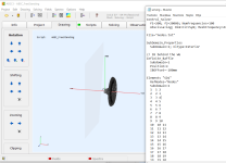
Code:
OSSE = {
  L = 60
  r0 = 8
  a0 = 5
  a = 65
  k = 1.7
  s = 0.76
  q = 0.996
  n = 4
}

Mesh.LengthSegments = 60
Mesh.AngularSegments = 8
;Mesh.SubdomainSlices =

Source.Shape = 1
ABEC.SimType = 1 ; 1= infinite baffle, 2= freestanding
ABEC.SimProfile = 0
ABEC.MeshFrequency = 43000
ABEC.NumFrequencies = 100
ABEC.Abscissa = 1
ABEC.f1 = 200
ABEC.f2 = 20000

ABEC.Polars:SPL = {
  MapAngleRange = 0,90,10
  NormAngle = 10
  Distance = 1  ;[m]
}

Output.ABECProject = 1
Output.STL = 0

Report = {
  Title = IB
  Width = 1600
  Height = 900
  GnuplotCode = rcirc-mono.gpl
  MaxRadius = 180
  MaxAnglePM = 90
}also, set
";Mesh.SubdomainSlices ="
and
"Mesh.InterfaceOffset = X"
where X is a positive value, often something like 2 or 3. Without parentheses.
";Mesh.SubdomainSlices ="
and
"Mesh.InterfaceOffset = X"
where X is a positive value, often something like 2 or 3. Without parentheses.
Returning to my comment above... these simulations show what is "emitted" in terms of FR (etc) looking around the simulated object (driver/WG) - but what would happen if we would define the emitting object to include also a "wall". Now, we could not simulated a room and stay circsym but what I have in mind is if one could just extend the simulated object with a r=1,5m disk just behind the WG as one (1) integral part... (ok one have to fit a real driver in the real world, but anyways...)
Would this simulation now take the wall into consideration and be valid for frequencies down to the size of the "wall-disc"?


//
Would this simulation now take the wall into consideration and be valid for frequencies down to the size of the "wall-disc"?


//
The above example/code uses no interface offset and it works fine."Mesh.InterfaceOffset = X"
where X is a positive value, often something like 2 or 3. Without parentheses.
The Infinite Baffle simulation takes the wall into consideration. That's what it does, only an infinite one. Finite baffle would be full of reflections from the edges - hardly useful. That's where you switch to a Free Standing simulation and consider such situation with all it takes.Returning to my comment above... these simulations show what is "emitted" in terms of FR (etc) looking around the simulated object (driver/WG) - but what would happen if we would define the emitting object to include also a "wall".
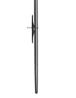
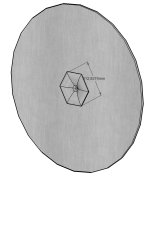
I'm afraid we're not exactly on the same page. What I'm trying to simulate is not an in-wall speaker, it's rather a cone-shaped speaker on a wall. The transducer is at the apex of the cone, a few cm in front of the actual wall. Perhaps this is the issue with the sim I did?
The idea behind the concept is this: an actual in-wall speaker that has transducers in the same plane as the wall, doesn't suffer from diffraction. If the on-wall cone is not very deep and it's large enough, the angle of incidence for the sound that reaches the wall is very high, such that comb-filtering will only be observed at high frequencies and close to the wall. In the real world, the result should be close to an actual in-wall speaker.
The idea behind the concept is this: an actual in-wall speaker that has transducers in the same plane as the wall, doesn't suffer from diffraction. If the on-wall cone is not very deep and it's large enough, the angle of incidence for the sound that reaches the wall is very high, such that comb-filtering will only be observed at high frequencies and close to the wall. In the real world, the result should be close to an actual in-wall speaker.
Ah, I see, I just didn't grasp that you would like to create something like that. What makes you think it doesn't work then? There will be reflections off the outer edge. I wouldn't expect it to be a lot cleaner...
I don't think so. Please enter a thought experiment with me. Say the baffle we're simulating is a flat circle with the same 155 mm radius in an infinite baffle. Then the result should be identical to a driver in an infinite baffle, because a flat baffle that's flush with an infinite baffle IS an infinite baffle. Next, we turn the R=155 mm circle into a very short cone, say a height of 1 mm. What has changed acoustically? Pretty much nothing. Yes, there's now a transition between the flat infinite baffle and the cone at the edge of the cone, but the cone is short that it's almost a flat circle. This will still behave like a driver in an infinite baffle.
At what height does the edge really become a source of significant diffraction? It depends on the angle and the wavelength. Is it even diffraction, or should we call this reflection instead?
At what height does the edge really become a source of significant diffraction? It depends on the angle and the wavelength. Is it even diffraction, or should we call this reflection instead?
Sure. A freestanding cone would be terrible, just as terrible as a freestanding flat circle. But a flush-mounted flat circle and a cone on an infinite baffle are completely different beasts.
One can add infinite baffle to ABEC sim, after you've created ABEC project with ATH, edit solving.txt manually and add something like this:
I think ATH put subdomain 1 for the outside so thats correct, but change Position=x to y or z, depending which plane is behind the waveguide. Use Offset to adjust distance. More info in ABEC help file.
Code:
Infinite_Baffle
  Subdomain=1
  Position=x
  IBOffset=-400mm
I think ATH put subdomain 1 for the outside so thats correct, but change Position=x to y or z, depending which plane is behind the waveguide. Use Offset to adjust distance. More info in ABEC help file.
Last edited:
I think it is diffraction as it is in essence an abrupt physical shape transition, just like the baffle edge.I don't think so. Please enter a thought experiment with me. Say the baffle we're simulating is a flat circle with the same 155 mm radius in an infinite baffle. Then the result should be identical to a driver in an infinite baffle, because a flat baffle that's flush with an infinite baffle IS an infinite baffle. Next, we turn the R=155 mm circle into a very short cone, say a height of 1 mm. What has changed acoustically? Pretty much nothing. Yes, there's now a transition between the flat infinite baffle and the cone at the edge of the cone, but the cone is short that it's almost a flat circle. This will still behave like a driver in an infinite baffle.
At what height does the edge really become a source of significant diffraction? It depends on the angle and the wavelength. Is it even diffraction, or should we call this reflection instead?
However the size is typically much less compared to a baffle of an enclosure. This makes it impossible to "separate" from the driver response.
This is why I think you should create an simulation object that also contains the wall. It will not be infinite and it will have to be round in order to be circ-sym or the simulation effort will be to big. But for a WG and and "built in wall" say 2m in diameter will give you ha hint down to wl/2 (?) - appr. 250 Hz?.... Say the baffle we're simulating is a flat circle with the same 155 mm radius in an infinite baffle.....
//
Yeah it's quite finicky, even small "issue" with waveguide profile makes diffraction already, doesn't have to be any sort of an edge but just "wrong" curvature that still looks smooth to eye but there is still ripple in frequency response plot. Also, there are some threads on this forum where I remember about 1mm gap / step with dome tweeter waveguide, either near the dome or at the rim, both show ripple in graphs. Basically ripple extends all the way down frequency whose wavelength is about diameter of the step/feature, which looks similar in graphs as diffraction so is likely diffraction. Whether this is audible is another question.I think it is diffraction as it is in essence an abrupt physical shape transition, just like the baffle edge.
However the size is typically much less compared to a baffle of an enclosure. This makes it impossible to "separate" from the driver response.
In theory it works fine to have speaker certain distance from the wall and have directivity high so that there is no sound toward edge/wall, but in reality there is some and it's impossible to get absolutely clean graphs even in simulator. What's clean enough is the question, and requires a listening experiment.
Keyser, Perhaps you've got some stuff we haven't seen yet here 🙂 Hopefully you share your results!
Tmuikki, I tried your suggestion. That didn't work out.
I'm currently just playing around with ATH, I figured this idea should work and I'm simply wondering why I'm not seeing the expected results.
I'm currently just playing around with ATH, I figured this idea should work and I'm simply wondering why I'm not seeing the expected results.
Last edited:
But a flush-mounted flat circle and a cone on an infinite baffle are completely different beasts.
Are you sure about that? I'm guessing here but I think it still is a disruption of the waveguide shape...
Maybe you can convince us with a picture of what it should look like. A side view would do.
For a cone in an infinite baffle - there will certainly be a lof of reflection (or diffraction, call it whatever you want, it's effectively a secondary source) at the points where the cone joints the baffle plane. This always happens if the wave cannot propagate further freely (i.e. undisturbed) - the cone doesn't continue further but hits the IB plane. As always, I suppose one could eliminate this with large radii, i.e. a smoother transition of the boundary. And I think concave boundaries, as in this case, are generally worse than convex.
- You could try a ripple tank, it should be obvious.
- You could try a ripple tank, it should be obvious.
Last edited:
You could try a ripple tank, it should be obvious.
Where did the quote post button go?
See, that helps... as I (and probably some others too) certainly imagined a waveguide in the other direction, you've flipped it inside out 😀.
- Home
- Loudspeakers
- Multi-Way
- Acoustic Horn Design – The Easy Way (Ath4)

