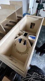
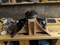
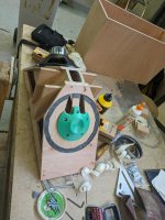
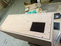
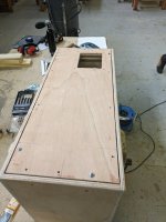
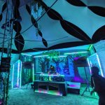
Have lurked for quite a while, and wanted to share the build I did back in October of last year, along with appearances at a couple events.
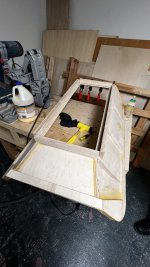
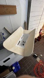
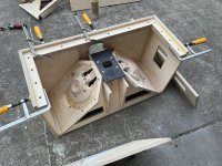
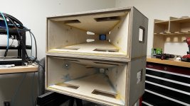
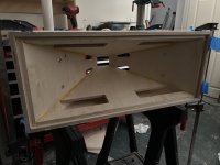
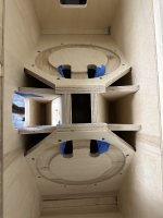
All of the miters were machine on a CNC using 3d surfacing operations--no saws involved in this build at all. Definitely incurs a lot of extra cycle time, but it meant I could avoid setting up jigs for those cuts.
I'm currently working on a v2 version of the CAD that's trying to be more faithful to @weltersys original design and fix some of the issues I had with the first one. More of those build progress and final assembly pics soon 🙂
Thanks to everyone in this thread who put so much work into documenting their process--simply could not have built this without you all <3
Attachments
-
 IMG_7125.jpeg381.4 KB · Views: 760
 -
 IMG_8418.JPG840.5 KB · Views: 720
 -
 IMG_7274.jpeg146.6 KB · Views: 748
 -
 IMG_8397.jpeg398.5 KB · Views: 684
 -
 IMG_8398.jpeg299.9 KB · Views: 689
 -
 IMG_8013.jpeg395 KB · Views: 635
 -
 IMG_7919.jpeg454.3 KB · Views: 626
 -
 IMG_7857.jpeg402.6 KB · Views: 633
 -
 IMG_7231.jpg804.9 KB · Views: 715
 -
 IMG_7215.jpeg350.1 KB · Views: 630
 -
 IMG_7196.JPG299.9 KB · Views: 615
 -
 IMG_7138.JPG330.8 KB · Views: 634

Hi guys, just wanted to ask if anyone took down the drive I had put up? went to check on it and nothing was in there. I could see from the logs someone had made everything private, which is just very creepy? Or maybe I'm infringing on their intelectual property? If I found the files they were public at some point so beats me.
Anyway it's back up and I added a readme file which contains an email address if there's anything on there that belongs to you and you don't want on the drive just leave me a message and I'll take it off.
https://drive.google.com/drive/folders/1Uc8v5Qk3jz8snis_ovhLCcN1j12PVRWf?usp=sharing
Regarding my project I've ordered fancy bolts and some other stuff and I'm struggling with mounting the HF driver still, but my V1 (I'm calling it a prototype cause it's rough haha) is coming along! V2 and onward will be planned out using Leosandstroms dope looking cad files for sure. I've got to convince the local fablab to turn their CNC machine back on for that adapter plate... Or maybe I can use the Shaper like i did for the horn ports, I'll see! My goal is now to have one functionning speaker by the end of the school year, and at least two good looking unequipped speakers!
Peace!
No Tone,
I would prefer the misspelling of "SynTripP" throughout your drive be corrected, but have no idea who changed your drive.
The "L.S.D." (Lake Street Dive) photo displays my 2x8" Paraline line array, not SynTripP cabinets.
The SynTripP is not designed to be used as a line array, so that photo should be taken down as out of context.
"Plans but not recommended by Art" would suggest I recommended other plans, which I haven't 😉
Art
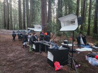
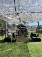
A cautionary note: at Burning Man this year a 50+MPH wind gust knocked over our 500+lb speaker stacks, the secondary horn makes quite a sail. We will now be anchoring the bass cabinets to the ground. Damage was substantial but not impossible to fix.
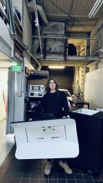
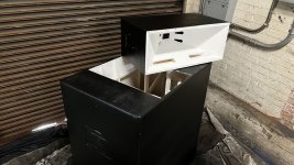
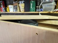
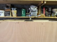
My mental fortitude is being tested. The HF driver doesn't fit in the box. I'll make it work. It might not be pretty but I'll make it work mark my words.
I made the throat adapter twice as thick as it should be. Plans said 12mm I made it 24 because of course I did!
I made the throat adapter twice as thick as it should be. Plans said 12mm I made it 24 because of course I did!
Attachments
-
 PXL_20230915_082623116.jpg333.9 KB · Views: 285
 -
 PXL_20230915_082554241.jpg462.5 KB · Views: 279
 -
 PXL_20230915_082547634.jpg385.8 KB · Views: 316
 -
 PXL_20230913_185039006.jpg440.9 KB · Views: 329
 -
 PXL_20230913_140626712.jpg544.3 KB · Views: 335
 -
 PXL_20230913_140622411.jpg587.6 KB · Views: 306
 -
 PXL_20230913_100946942.jpg501.8 KB · Views: 282
 -
 PXL_20230913_100917793.jpg521.9 KB · Views: 276
how are you anchoring them to the ground?A cautionary note: at Burning Man this year a 50+MPH wind gust knocked over our 500+lb speaker stacks, the secondary horn makes quite a sail. We will now be anchoring the bass cabinets to the ground. Damage was substantial but not impossible to fix.
Due to the array of unknowns both below and above the surface of any anchoring application – the soil medium, installation method, local climate, connections to the anchored structure – no one can guarantee a specific holding strength for ground anchors.A cautionary note: at Burning Man this year a 50+MPH wind gust knocked over our 500+lb speaker stacks, the secondary horn makes quite a sail. We will now be anchoring the bass cabinets to the ground. Damage was substantial but not impossible to fix.
https://americanearthanchors.com/load-capacity/
After having stacks blown down, and typically not being able to find available secure anchor points, decided to build plinths to ratchet strap the stack to for stability. The stack happened to be 500+lb, and the plinth securing it according to the calculations to 54 MPH wind gusts.
You may be interested in the discussion of the math behind the sizing of the plinth:
https://forums.prosoundweb.com/index.php?topic=118012.0
Re: Wind Speed and Speaker Stack Tipping Point Questions
« Reply #23 on: August 19, 2009, 11:59:13 PM »
Peter,
The problem with the discrepancies between the measured tip and the equations you provided were due to the way the scale was used.
When compensating for the scale inaccuracies, the measured results match the equations you provided almost exactly.
Thanks again!
It turns out that the bathroom scale used reads quite a bit lower when the force is applied to the center rather than the outside.
The scale is designed for use with two feet stepping on the sides, center weight causes the platform to deflect, and lowers the reading.
Using the jack, which center loads the scale, reads only 155 pounds when 195 (or more) is actually applied.
As Homer Simpson says, “Doh!”.
I built a pair of 45 x 45 inch plinths made from 2 pieces of LP SmartSide Engineered Wood Siding panel laminated together weighing 37 pounds each. With the large plinth, the stretch in the ratchet strap webbing became apparent, a lot more strap tension to keep the aft end of the cabinets tight to the plinth was needed than is required to simply keep the cabinets from “wobbling”.
The math with the plinth:
507 * 22.5=11407.5/57.=200 pounds stabilizing moment
197 =20.7*47^2*.00431 (wind force is less than stabilizing moment)
47 knots *1.150778 =54 MPH
This appears to be a bit more stable than a pair of stacked EAW KF 850zR:
412*14.75+6077/42.37=143 pounds stabilizing moment
141.69=15.88*45.5^2*.00431 (wind force is less than stabilizing moment)
45.5 knots *1.150778 =52.36 MPH
The KF 850zR center of balance is a little aft of center (15.75 inches, not 14.75, which is half the 29.5 depth) but it is a trap cabinet, so the back area is smaller than the front, so the wind tip factor is probably pretty close with a front or rear wind.
And more stable than a pair of Clair Brothers S-4 cabinets (440 pounds, 45 x45 x 22.5, 28.125 square feet “sail area”) strapped together would just withstand a 48.9 MPH wind.
880 *11.25=9900/45=220 pounds stabilizing moment
218.95=28.125*42.5^2*.00431 (wind force is less than stabilizing moment)
42.5 knots *1.150778 =48.9 MPH
I don’t have exact weights or center of balance for the S-4, newer versions reduced the weight by using a composite back panel, which would shift the center of balance forward, reducing the above wind resistance calculation a bit.
Anyway, thanks for providing the math that makes me feel safe knowing my stack with the plinth is more stable than stacked “old standards” .
Art Welter
@kipman725 yeah I thought about that but I'm just going to remake the HF driver adapter plate since that's where the error was 🙂
Quick gratitude post for Art's designs. We collected quite a few compliments for sound quality at our little camp at the Burn, and our pockets are far less deep than a lot of the builds we saw/heard there. A neighboring camp actually had 8 keystones going with some custom 2x14 tops. The builder was impressed with the SyntripPs.
Thanks again, Art!
Thanks again, Art!
Attachments

how are you anchoring them to the ground?
We use a ratchet strap over the top of the bass bin anchored to the ground with 14” lag bolts. Hat was for a very dry, solid ground. Wouldn’t work with dirt and a lawn though…
Wow great post and suggestion. We will calculate it out…Due to the array of unknowns both below and above the surface of any anchoring application – the soil medium, installation method, local climate, connections to the anchored structure – no one can guarantee a specific holding strength for ground anchors.
https://americanearthanchors.com/load-capacity/
After having stacks blown down, and typically not being able to find available secure anchor points, decided to build plinths to ratchet strap the stack to for stability. The stack happened to be 500+lb, and the plinth securing it according to the calculations to 54 MPH wind gusts.
You may be interested in the discussion of the math behind the sizing of the plinth:
https://forums.prosoundweb.com/index.php?topic=118012.0
Re: Wind Speed and Speaker Stack Tipping Point Questions
« Reply #23 on: August 19, 2009, 11:59:13 PM »
Peter,
The problem with the discrepancies between the measured tip and the equations you provided were due to the way the scale was used.
When compensating for the scale inaccuracies, the measured results match the equations you provided almost exactly.
Thanks again!
It turns out that the bathroom scale used reads quite a bit lower when the force is applied to the center rather than the outside.
The scale is designed for use with two feet stepping on the sides, center weight causes the platform to deflect, and lowers the reading.
Using the jack, which center loads the scale, reads only 155 pounds when 195 (or more) is actually applied.
As Homer Simpson says, “Doh!”.
I built a pair of 45 x 45 inch plinths made from 2 pieces of LP SmartSide Engineered Wood Siding panel laminated together weighing 37 pounds each. With the large plinth, the stretch in the ratchet strap webbing became apparent, a lot more strap tension to keep the aft end of the cabinets tight to the plinth was needed than is required to simply keep the cabinets from “wobbling”.
The math with the plinth:
507 * 22.5=11407.5/57.=200 pounds stabilizing moment
197 =20.7*47^2*.00431 (wind force is less than stabilizing moment)
47 knots *1.150778 =54 MPH
This appears to be a bit more stable than a pair of stacked EAW KF 850zR:
412*14.75+6077/42.37=143 pounds stabilizing moment
141.69=15.88*45.5^2*.00431 (wind force is less than stabilizing moment)
45.5 knots *1.150778 =52.36 MPH
The KF 850zR center of balance is a little aft of center (15.75 inches, not 14.75, which is half the 29.5 depth) but it is a trap cabinet, so the back area is smaller than the front, so the wind tip factor is probably pretty close with a front or rear wind.
And more stable than a pair of Clair Brothers S-4 cabinets (440 pounds, 45 x45 x 22.5, 28.125 square feet “sail area”) strapped together would just withstand a 48.9 MPH wind.
880 *11.25=9900/45=220 pounds stabilizing moment
218.95=28.125*42.5^2*.00431 (wind force is less than stabilizing moment)
42.5 knots *1.150778 =48.9 MPH
I don’t have exact weights or center of balance for the S-4, newer versions reduced the weight by using a composite back panel, which would shift the center of balance forward, reducing the above wind resistance calculation a bit.
Anyway, thanks for providing the math that makes me feel safe knowing my stack with the plinth is more stable than stacked “old standards” .
Art Welter
Great Looking model here Leo! Can you by chance supply me this as a .step file? I don't really want to make an Onshape account, just to export the files. That would be very much appreciated if possible. Alex.I've had a total of eight people email me the past days asking for my plans so I thought I'd just post them here! You should be able to either clone everything to your own OnShape account, or just export the parts in your preferred format.
https://cad.onshape.com/documents/7...09e6c8fa05c7e109e9/e/cbf888de0316d2db8b70b557
The model features pretty much everything, including the grill frame, secondary horn, handles, adjustable pole mount, dado joints, drill holes, rubber feet, and a neutrik connector that's separate from the rear panel.
Some quick notes:
I've been working on this model on and off for the last 6 months, so things are a bit messy and I can't guarantee that all measurements and angles are 100% correct. I know for sure that I've performed some rounding here and there, but there shouldn't be any large deviations (except for the above of course).
- The throat adapter is similar to ones posted earlier in this thread and allows for easy removal of the compression driver, using short studs on the driver and nuts for mounting. I have compared the throat shape to
SynTripP_throatadapter_v04by @Jennygirl and they're pretty much spot-on identical.- The profile for the phase plug is derived from
SynTripP_coneplug_v08by @Jennygirl, with some minor changes to the fillet. Do note that I've created a recess for easier mounting, meaning that the phase plug has been extended 5mm. If you were to use the cone plug as-is without the recess, it's guaranteed to interfere with the speaker cone/dustcap!- In order to fit the Adam Hall SM707 pole mount I had to increase the gap between the BR port sides by about 1cm.
- The secondaries deviate from the original sketches by having slightly longer sides and rounded top/bottom panels.
If you find any issues, please let me know!
View attachment 1182767View attachment 1182766
View attachment 1182768View attachment 1182769
View attachment 1182774
Hi folks.Is it close enough?
Hi folks, do you think these 10” Triton drivers can kind of replace the B&C one for this project?
It seems they can’t get as low and are not as strong, but they are way cheaper here in Brazil, and since the CD is starting it’s response so low, I thought it would probably be maxed out before these Triton 10” drivers, even though they are not perfect for the horn.
I know the best way to find out is to get them and test it, but maybe someone can find an obvious reason why they wouldn’t work…
I’m attaching both the Triton and the B&C datasheets.
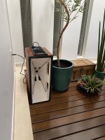
I finally made it. Or made something close. I mean, kind of. ahahahaha
Keep in mind that I only spent ~550 dollars for whole solution here in Brazil, so the expectations must be managed.
Also, I tried a Boombox approach, with that Plate Amp with a (limited) DSP, with claimed 600w for the lows and 200w (4 ohms) for the highs (and bluetooth!).
It came out pretty heavy and sounds ok, but I feel I might be missing something in regards of tuning. I only have 6 bands per channel, though.
Although being more useful in horizontal, I have found its dispersion in vertical mode enough for most use cases. I've been using it for a couple months now, and it is, DEFINITELY, a JBL Partybox killer, with superior sound quality AND SPL and for a better price down here.
Tell me about your opinions and thoughts about this unusual use of Art's project. I'm curious about what these naive and not optimal things I did brings to the table.
Btw, I'm thinking about an active version of a tapped horn, maybe the Keystone itself, using the same cheap local drivers concept, to put together a large-space solution.
Attachments

Last edited:
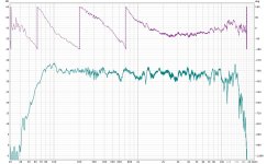
The (unsmoothed) tuning response looks good, does not look like you are missing much other than the lightshow and strobes in the JBL Partybox!
Hi everyone,
Wow, more than a year has happened since my last reply to this thread!
We ended up ditching the whole (pretty naive, as noted by Art) fiberglass idea, and thanks to the wonders of CNC machining and the generosity of the Barcelona city hall in lending us a space and tools to work with, we managed to successfully complete the build in spite of our lack of woodworking experience.
Our SynTripPs are loaded with the original B&C 10 inch drivers and a RCF Nd840 compression driver. RCF use it in some of their Art 9 cabinets crossed as low as 700hz, so I was confident that it can handle the 800hz crossover point required by the SynTripP design. So far they have been working great!
We are using an oversized secondary expansions to extend pattern control lower (we haven't tested by how much with a full spinorama yet though). To anybody reading this, please note that our version eliminates the grill frame, which is NOT recommended by Art. If we were to build them again, I would add the grill frame in order to have the option (even if I'm absolutely in love with the looks without the grill).
We have used the SynTripPs filtered by a T.Racks DSP 206 and powered by a single T.amp TSA 4-700 on four separate occasions during the summer, both indoors and outdoors and for audiences up to 300 people. Both the dsp and amp have performed flawlessly, but the amp is gonna get swapped for something more powerful very soon, as according to my experience it can hit the clip lights on the mid channels without bringing the dual 10" to their excursion limits.
We have received tons of compliments both on sound quality and looks.
When I first stumbled into this thread 18 months ago, I had absolutely no clue about speaker design and 90% of what's been discussed here went way over my head. Since then, I have become obsessed. I've read more threads on this and similar forums than I could count, I've learned how to simulate and measure enclosures, the tradeoffs of different types of loading, etc. And of course I've only scratched the surface yet.
So Art, thanks for the amazing design, but most importantly thanks for providing a "gateway" into the beautiful world of speaker DIY.
Attachments


Semabr,
Nice work, you really dived in to the deep end for your "gateway" into the beautiful world of speaker DIY!
Looking forward to seeing measurements to see how the RCF Nd840 compares.
Art
Nice work, you really dived in to the deep end for your "gateway" into the beautiful world of speaker DIY!
Looking forward to seeing measurements to see how the RCF Nd840 compares.
Art
Celestion just announced an updated version of the CDX14-3050: the CDX14-3055.
https://celestion.com/product/cdx14-3055/
Slightly smaller dimensions but with increased sensitivity (106.5 vs 108), higher power rating (150 watts vs 240 watts), and most importantly, a lower minimum crossover point (1000hz vs 800hz).
The lower crossover point seems particularly exciting for SynTripP builds, where it can be challenging to get the CD to meet the mids with the 3050.
Would love to hear your thoughts @weltersys !
My thoughts are the measurements, other than the plane wave tube are not comparable between the drivers, as different horns are used, the CDX14-3055 on 90x40 vs 80x60 for the CDX14-3055.

Looking at the plane wave tube measurements, more smoothing has been applied to the newer driver, but it's sensitivity looks similar, if anything slightly less.
Hopefully the driver to driver consistency would be better than the units I used, but I'm not too excited about the changes.
Art
Looking at the plane wave tube measurements, more smoothing has been applied to the newer driver, but it's sensitivity looks similar, if anything slightly less.
Hopefully the driver to driver consistency would be better than the units I used, but I'm not too excited about the changes.
Art
Hi all,
If one was to want to make these active. If modifying the box design, do I just need to keep the box volume the same? Otherwise I have considered a very easy option using the same box as per plans, but making the removable back panel a box that will house the amp (essentially just a box that straps to the back.)
This will have a 2 channel DSP amp that should make a nice all in one top. 🙂
Excited to start the build!
- Home
- Loudspeakers
- Multi-Way
- SynTripP: 2-way 2-part Virtual Single Point Source Horn