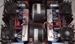
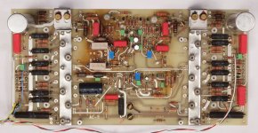
Thank you Hans. Actually the resistor values are correct. As you can see in the photos I posted the 20 ohm resistors are the big brown ones close to the heatsink transistors.
Ok I will double check when I can. However by looking at the pictures I can’t see any other resistors nearby, other than the 20R, 10R, and the two 60R ones
Please measure with the amp switched on the voltage over the 20R resistors and also between the emitters, then we know how much current the amp is drawing.
Hans
Hans
Hans I confirm that the emitter resistors are 10R and 20R. Resistance between emitters is 30 ohms.
In the negative regulator:
Voltage across the 20R resistor is 4.2V (other channel is 3.9V).
Voltage across the emitters is 4.5V (other channel 3.9V).
On the positive regulator side, the voltages are:
Across 20R: 4.3V (other channel 3.9V).
Across emitters: 4.5V (other channel 3.9V)
In the negative regulator:
Voltage across the 20R resistor is 4.2V (other channel is 3.9V).
Voltage across the emitters is 4.5V (other channel 3.9V).
On the positive regulator side, the voltages are:
Across 20R: 4.3V (other channel 3.9V).
Across emitters: 4.5V (other channel 3.9V)
O.k. 4.3 volt over 20R means 215mA.
And 4.5 minus 4.3Volt over 10R means 20mA.
So the Amp is drawing 215-20mA=195mA, quite a lot for just one preamp channel.
I didn’t expect that.
The second channel however is suppplying also 195mA but the second transistor is not doing anything.
Later today I’ll make the sim and let you know what the optimal setting is.
Hans
The answer is quite simple.
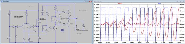
With 10mA DC current flowing in the 10R resistor, Output voltage becomes unstable when switching the output current between 195mA and 205mA.
With 20mA or with below 1mA output stays stable with this switching load signal.
See first image below showing the output voltage with resp 20mA and 10mA DC through 10R.
Blue is the switching load current and Red the effect on the output voltage for both 10mA and 20mA DC.
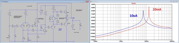
Looking at the Power Supply Rejection Ratio for 0mA and 20mA, its obvious that below 10Khz, PSRR for the 20mA version is superior.
See second attachment.
Conclusion, set the pot to 20mA DC current for the 10R resistor.
Hans
With 10mA DC current flowing in the 10R resistor, Output voltage becomes unstable when switching the output current between 195mA and 205mA.
With 20mA or with below 1mA output stays stable with this switching load signal.
See first image below showing the output voltage with resp 20mA and 10mA DC through 10R.
Blue is the switching load current and Red the effect on the output voltage for both 10mA and 20mA DC.
Looking at the Power Supply Rejection Ratio for 0mA and 20mA, its obvious that below 10Khz, PSRR for the 20mA version is superior.
See second attachment.
Conclusion, set the pot to 20mA DC current for the 10R resistor.
Hans
Attachments
Very impressive! Thanks.
I set all pots for 20mA. I wonder why on one channel they were turned all the way to 0mA, while on the other channel they were set for 25mA
Why did you chose these values? Did you do simulations with other current values ans well? Any advantages in setting a higher current?
I set all pots for 20mA. I wonder why on one channel they were turned all the way to 0mA, while on the other channel they were set for 25mA
Why did you chose these values? Did you do simulations with other current values ans well? Any advantages in setting a higher current?

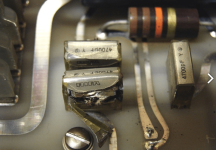
You mean the Type 88D in the PLS-226 powersupply?It’s a pitty they repaced the square Spraque caps, they are very expensive and undestructable.
Hans
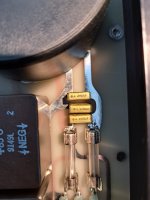
And how about the EMI suppression caps (Rifa PME271) that gave problems in the powersupply PCB of the No. 23 amp and that are also in the PLS-226 powersupply for the No. 26 and No. 25?
Attachments
Last edited:
Okay I will download some datasheets to get a drop-in replacement for them.
Do you have any experiences with the No. 23/No 23.5 amps.
I've had the Levinson ML-3 it's predecessor which was very easy to service because of its size but the No. 23 looks to me very cramped and servicing could become very timeconsuming if you would like to perform a caprevision on the outputboards with the silver (672D) Spragues.
Attachments
Yes, I've quite some experience with these amps.
The 23 is easier to service, because the 23.5 still has an additional piggybacked board on top.
Keep in mind these amps are rather old ladies, never made with serviceability in mind and PCB's aren the best in the industry.
So repair can be quite challenging.
Hans
The 23 is easier to service, because the 23.5 still has an additional piggybacked board on top.
Keep in mind these amps are rather old ladies, never made with serviceability in mind and PCB's aren the best in the industry.
So repair can be quite challenging.
Hans
Okay, thanks for this information. Serviceability is a key factor for old electronic equipment so the No. 23/No 23.5 is a no go for me.Keep in mind these amps are rather old ladies, never made with serviceability in mind and PCB's aren the best in the industry.
So repair can be quite challenging.
- Home
- Amplifiers
- Solid State
- Mark Levinson 26 calibration