Hello,
I just bought a ML 26 with internal MC phono stage, which I've been dreaming about for the past 2 years 😀
It works flawlessly so I'm just doing regular maintenance, replacing electrolytic caps and checking that voltages are ok. Does anyone know the calibration procedure for this preamp? There are several trimpots in the regulator section, line stage and phono stage.
Thanks
Up.
Nobody knows about this? There are schematics available but my knowledge is limited understand the calibration procedure.
Nobody knows about this? There are schematics available but my knowledge is limited understand the calibration procedure.
I suggest you post a schematic to make easier for members to offer advice.
Good luck!
Good luck!

you're right 😅
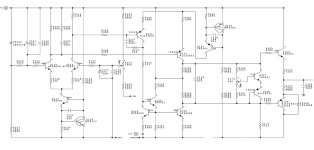
attached are the schematics. there's two pots each on the negative and positive regulators, and two pots on the line stage.
attached are the schematics. there's two pots each on the negative and positive regulators, and two pots on the line stage.
Attachments
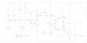
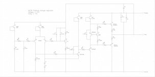
Pot(s) I2 in each regulator would be used to trim the +/- 17V outputs to their respective nominal voltages. Also, each regulator has a bias spreader, adjusted via I7. Push/pull archetecture is very unusual for a purported power supply regulator. This, and the quandary of how to adjust I7, prompted me to dig a little deeper.
IMHO, the posted schematic is probably a DIY effort to reverse engineer a schematic. A great effort, but I believe there is an error in the depicted bias spreader circuit. If the circuit were as depicted, the voltage across C5 would be about 5V--- enough to drive output complimentary pair into massive conduction. But if you measure the voltage across C5, I predict you'll find a bit over 0.6V. In short, the I7 pot won't have much effect and you shouldn't worry about it.
IMHO, the posted schematic is probably a DIY effort to reverse engineer a schematic. A great effort, but I believe there is an error in the depicted bias spreader circuit. If the circuit were as depicted, the voltage across C5 would be about 5V--- enough to drive output complimentary pair into massive conduction. But if you measure the voltage across C5, I predict you'll find a bit over 0.6V. In short, the I7 pot won't have much effect and you shouldn't worry about it.
Thank you for your time! Indeed the schematics have been posted by a forum user a while ago. I suppose an error could be possible.
Thanks I will check the voltages as you suggested.
Any hints on the line stage?
Thanks I will check the voltages as you suggested.
Any hints on the line stage?
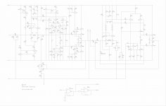
Sorry, I forgot to mention line stage. First use pot I27 to null Out+, then use I10 to null Out-.
You are right that the resistor values are odd and must be dead wrong.Pot(s) I2 in each regulator would be used to trim the +/- 17V outputs to their respective nominal voltages. Also, each regulator has a bias spreader, adjusted via I7. Push/pull archetecture is very unusual for a purported power supply regulator. This, and the quandary of how to adjust I7, prompted me to dig a little deeper.
IMHO, the posted schematic is probably a DIY effort to reverse engineer a schematic. A great effort, but I believe there is an error in the depicted bias spreader circuit. If the circuit were as depicted, the voltage across C5 would be about 5V--- enough to drive output complimentary pair into massive conduction. But if you measure the voltage across C5, I predict you'll find a bit over 0.6V. In short, the I7 pot won't have much effect and you shouldn't worry about it.
But ML uses push/pull topology in many amps, like for instance in the ML 300 series.
See attachment where you see large differences between upper and lower resistance values in the endstage.
One transistor is supplying the current and the other one is a sort of ripple eater.
Hans
Attachments
Thanks! Interesting.
I'm guessing the "-REG" connects to the output, but it hooks up off-screen somewhere? I wonder what is the intent of the push-pull drive with the wildly (100x) unbalanced emitter resistors?
I'm guessing the "-REG" connects to the output, but it hooks up off-screen somewhere? I wonder what is the intent of the push-pull drive with the wildly (100x) unbalanced emitter resistors?
Ok I checked the voltages. Actually voltage across C5 is around 5V. Anything I should do with the pot I7?Pot(s) I2 in each regulator would be used to trim the +/- 17V outputs to their respective nominal voltages. Also, each regulator has a bias spreader, adjusted via I7. Push/pull archetecture is very unusual for a purported power supply regulator. This, and the quandary of how to adjust I7, prompted me to dig a little deeper.
IMHO, the posted schematic is probably a DIY effort to reverse engineer a schematic. A great effort, but I believe there is an error in the depicted bias spreader circuit. If the circuit were as depicted, the voltage across C5 would be about 5V--- enough to drive output complimentary pair into massive conduction. But if you measure the voltage across C5, I predict you'll find a bit over 0.6V. In short, the I7 pot won't have much effect and you shouldn't worry about it.
I used pot I2 to set the +/-17V, except on one channel where moving the pot doesn’t affect the voltage on the negative regulator. However the voltage is 17.1V so I can leave it as is or is it a weird behavior and need further investigation?
Actually, it seems that everything is a bit weird, and I believe it needs to be understood, at minimum. Do you see any evidence that the preamp has been "serviced" before?
I've never even seen a ML device before; I can only project what should happen from looking at the schematic, and there's unconfirmed suspicion that the schematic may not be correct. I assume you observe about 5V across C5 in both regulators? What are the unregulated supply voltages for each regulator?
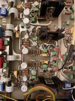
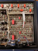
I hope a DIY owner will confirm what constitutes nominal operating voltages and installed part values. Would you post a few internal pictures?
I'll comment on what I observe in the schematic. The 14k and 8.87k resistors are consistent with 17V supplies derived from 6.6V Zeners, so that's promising. Focusing on the -17V regulator, the 3.48k,100 Ohm pot, 383 Ohm string is baffling; assuming Vbe is 0.6V, the bias spreader voltage across C5 would be at least 5.91V. Again on the -17V supply, would you report voltages re ground on:
Vsupply
C5, both top and bottom terminals
I2 pot, all three terminals
base of MAT02 at R1
Maybe that will help determine what's happening.
Thanks!
I've never even seen a ML device before; I can only project what should happen from looking at the schematic, and there's unconfirmed suspicion that the schematic may not be correct. I assume you observe about 5V across C5 in both regulators? What are the unregulated supply voltages for each regulator?
I hope a DIY owner will confirm what constitutes nominal operating voltages and installed part values. Would you post a few internal pictures?
I'll comment on what I observe in the schematic. The 14k and 8.87k resistors are consistent with 17V supplies derived from 6.6V Zeners, so that's promising. Focusing on the -17V regulator, the 3.48k,100 Ohm pot, 383 Ohm string is baffling; assuming Vbe is 0.6V, the bias spreader voltage across C5 would be at least 5.91V. Again on the -17V supply, would you report voltages re ground on:
Vsupply
C5, both top and bottom terminals
I2 pot, all three terminals
base of MAT02 at R1
Maybe that will help determine what's happening.
Thanks!
Ok, I will check more precisely all those voltages and report back to you. For now I can tell you that the preamp has been serviced about 10 years ago by a “reputable” technician here in Italy, but honestly I don’t like the job he did. He replaced all 68uF sprague capacitors with 100uF ones for no reason, and replaced the original squared sprague capacitors on the power supply with general purpose Vishay ones. Plus some solder joints did not look great. But overall the amp worked and sounded well when I got it. I replaced the original sprague capacitors (NOS and measured perfectly in every aspect) and all original values capacitors. As far as the schematics, the resistor values I checked so far are all correct, but didn’t check them all yet. I will post detailed photos. The ~5V across C5 is for both positive and negative regulators, on both channels (it’s a dual mono design).
Regarding the channel whit the negative regulator issue I mentioned, actually the pot does work, but it needs to be turned all the way to reach -17.2, if I move it from there I can only go more negative. It’s ok because I can set the proper voltage but the adjustable range is not correct
Regarding the channel whit the negative regulator issue I mentioned, actually the pot does work, but it needs to be turned all the way to reach -17.2, if I move it from there I can only go more negative. It’s ok because I can set the proper voltage but the adjustable range is not correct
It’s a pitty they repaced the square Spraque caps, they are very expensive and undestructable.
Hans
Hans
I agree. I paid 400$ for four NOS ones. Crazy but in the end well worth it sound wise, they are the only caps that make the 28 and 26 really sing, I’ve tried a few alternatives. The sprague seem really indestructible, capacitance is all +10-20% than specified, ESR unmeasurable with my peak meter (0.00 ohms), even after 20-30 years on the shelf. They don’t make such components anymore.
Ok here are the measurements:Actually, it seems that everything is a bit weird, and I believe it needs to be understood, at minimum. Do you see any evidence that the preamp has been "serviced" before?
I've never even seen a ML device before; I can only project what should happen from looking at the schematic, and there's unconfirmed suspicion that the schematic may not be correct. I assume you observe about 5V across C5 in both regulators? What are the unregulated supply voltages for each regulator?
I hope a DIY owner will confirm what constitutes nominal operating voltages and installed part values. Would you post a few internal pictures?
I'll comment on what I observe in the schematic. The 14k and 8.87k resistors are consistent with 17V supplies derived from 6.6V Zeners, so that's promising. Focusing on the -17V regulator, the 3.48k,100 Ohm pot, 383 Ohm string is baffling; assuming Vbe is 0.6V, the bias spreader voltage across C5 would be at least 5.91V. Again on the -17V supply, would you report voltages re ground on:
Vsupply
C5, both top and bottom terminals
I2 pot, all three terminals
base of MAT02 at R1
Maybe that will help determine what's happening.
Thanks!
Vsupply +/- 28.8V on one channel and +/- 29.6V on the other
C5 top terminal -16.12V bottom terminal -21.95V (Other channel -16.66V and -21.61V, respectively).
I2 Top terminal: -6.28V (other channel -6.34V); central terminal: -6.99V (other channel -6.88V); bottom terminal: -6.99V (other channel -7.02V).
Base of MAT02 at R1: -6.98V (other channel -6.88V).
Everything seems simmetrical so far except in order to get -17V on one channel pot I2 is turned all the way while on the other is turned half way.
I attach a few pictures.
Attachments
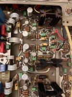
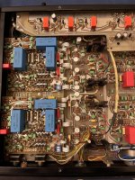
Pretty equipemnt.
I've come to believe that ML actually intends the unusually large base spreader voltage, so I think you don't need to do anything. I doubt the exact voltage at the -17V regulator is critical--- just stable, low noise regulation is the likely objective. It you want to trim the -17V supply to nominal, decrease the 14K resistor appropriately.
I've come to believe that ML actually intends the unusually large base spreader voltage, so I think you don't need to do anything. I doubt the exact voltage at the -17V regulator is critical--- just stable, low noise regulation is the likely objective. It you want to trim the -17V supply to nominal, decrease the 14K resistor appropriately.
Let me simulate the circuit and give you the answer.
In the meantime you could measure the two emitter resistors, one of both is wrong in the given circuit diagram.
I suspect the 10R is o.k. but the 20R is likely to be 200R.
Hans
In the meantime you could measure the two emitter resistors, one of both is wrong in the given circuit diagram.
I suspect the 10R is o.k. but the 20R is likely to be 200R.
Hans
- Home
- Amplifiers
- Solid State
- Mark Levinson 26 calibration