I can't isolate the sound. I was thinking of swapping out this transformer and use a 4218 just to see if i can isolate it to the transformer.
Or i could swap out the PSU board?
I realize now how lucky I've been to dodge the hum issues.
Or i could swap out the PSU board?
I realize now how lucky I've been to dodge the hum issues.
Some transformers just hum. It can be annoying if it's loud but doesn't hurt anything. Try swapping it if you have another to test with. If it was a recent purchase you might be able to exchange it. If you overload the transformer it will usually make more of a buzzing noise.
Might double check the blue and green secondary wires are connected. In other words, pull the blue and green off one rectifier bridge and make sure it measures a nice low resisitance with power off.
can you say more about overloading the transformer?Some transformers just hum. It can be annoying if it's loud but doesn't hurt anything. Try swapping it if you have another to test with. If it was a recent purchase you might be able to exchange it. If you overload the transformer it will usually make more of a buzzing noise.
Overloading would most likely be the shorted turn scenario you just ruled out with the rubber mat insulation. It's possible there's an error in the supplies causing a short but not likely if they're a proven design. As RickRay suggested verify the secondary windings are in fact connected correctly. Are you getting correct voltages at the output of the supplies? Have you powered up the supplies with a bulb limiter connected in the mains? Does the bulb die out after a couple seconds?
Some transformers get upset from solar inverters and other forms of grid pollution. You can get a lead by testing if it is less noisy at night.
The torque on the central bold can make a huge difference.
Torrid require a silicone disk at top and bottom.
You can try to pot the transformer, but this is costly, irreversible and without warranty.
Buy a transformer that is designed for audio.
The torque on the central bold can make a huge difference.
Torrid require a silicone disk at top and bottom.
You can try to pot the transformer, but this is costly, irreversible and without warranty.
Buy a transformer that is designed for audio.

I had one "buzz". I did not know what was inside (the windings) ? It got quiet if I pushed on it or changed it's position.
I saw after unwinding it , it was a roll of flat steel stock without much varnish. I was expecting something like a EI with lots of varnish.
I saved the windings but noticed the flat stock was pretty loosely wound.
I assumed the loose steel was the cause of the "buzz".
(below) I watch people wind toroids on youtube , some use a nice cast ferrite core instead of rolled steel.
Wonder if Antec uses ferrite ? Never had one of those make any noise at all.
OS
Attachments
I put in a Antek 400VA 24V transformer. No hum. But 2 differences: 1] this transformer has a ground wire which i hooked up. And 2] there are no 12V and 18V secondaries on it.
I will swap in the 800VA 45V transformer. Maybe it is the transformer?
I will swap in the 800VA 45V transformer. Maybe it is the transformer?
Swapped the 800VA back in. Hum is slightly worse.
What other brands should I consider vs. Antek?
Thanks,
What other brands should I consider vs. Antek?
Thanks,
How old is it? They will normally replace it if you have issues. They're slow to respond but do eventually.
Have you considered using a pair of 400VA instead? This makes it easier to eliminate ground loops.
Have you considered using a pair of 400VA instead? This makes it easier to eliminate ground loops.
Jwilhelm,
I called Antek today and talked with John. He patiently worked with me, had me send a photo and decided he will send me a new unit and a return label so I can return this one to him.
So we will see. More will be revealed.
I'll start building a amp card.
I called Antek today and talked with John. He patiently worked with me, had me send a photo and decided he will send me a new unit and a return label so I can return this one to him.
So we will see. More will be revealed.
I'll start building a amp card.
Hi Folks,
Quick question regarding insulators on the larger transistors. I see in the build guide that mica insulators with thermal paste are recommended. Would a thermal pad such as the Keratherm pad work also? I'm putting together another parts order and wondering if the mica/grease combo was recommended for a specific reason.
Thank you in advance. Dave M.
Well, I have searched and not found clarification for the LC cap. I am reading that the default choice is a 2pF cap. What is the power rating I should target for a 2pF mica cap? Can I go with 300V. That appears to be the lowest I can find currently. Reading the BOM this way:
2pF = 3V
10pf = 500V
Am I thinking about this correctly?
Thanks,
2pF = 3V
10pf = 500V
Am I thinking about this correctly?
Thanks,
LC = lead compensation.... While this was added to most of my "blameless" designs (badger/wolverine).Well, I have searched and not found clarification for the LC cap. I am reading that the default choice is a 2pF cap. What is the power rating I should target for a 2pF mica cap? Can I go with 300V. That appears to be the lowest I can find currently. Reading the BOM this way:
"Lead compensation sacrifices the bandwidth between the 1/RFC breakpoint and the forward gain curve".
It (Clead) , is not really needed if you use reasonable values for the main TMC compensation. I added it for some who wanted to push
the amp to it's limit.
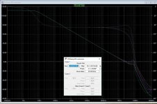
(Below) is a compensation plot with a .2 - 5pF Clead , note the change in phase as the value is stepped upward.
On a square waveform , increasing Clead will damp "ringing" on the resulting waveform.
Going in the other direction , I've used this type design to run subwoofers .... Just a single main 100pF cap at VAS - no lead or TMC.
Your ears might not hear these changes , but 20Khz THD would increase.
Read - https://www.rcet.org.in/uploads/academics/rohini_28552497983.pdf
OS
Attachments
- Home
- Amplifiers
- Solid State
- diyAB Amp The "Honey Badger" build thread