E180F sounded glorious to me, though not necessarily low distortion. Shootout between E180F, 6N6P, 6Z51P, 6J5.
None of them sounded bad. E180F I found to be special, but 6J5 and 6Z51P cleaner and more neutral to my ear.
This was also in a shootout where I varied using just a cathode resistors (for above-mentioned tubes) and LEDs. LEDs were so much better with respect to bass. Relevant to this discussion, all tubes were loaded with Ale Moglia's gyrators. I think they sound great with my 6J5 but there are many parts and I have experienced two failures (both my fault). If a tube CCS can replace one with decent sound, I'd probably do that in a subsequent build instead of a gyrator.
I'm very curious about how this will sound. Would much rather use a tube than a solid-state CCS for heat dissipation reasons, just as you say, though you will of course have additional heat under the chassis by adding another tube.
IMO embrace putting cathode resistors on top or building into the design, somehow. Recently reworked a PSU and added two new resistors that get pretty hot. They are under the chassis and ventilated with holes but the chassis still gets plenty warm in that area.
Looked at a couple resources for vacuum tube-based CCS. One of course is Mr Tubelab:
- http://tubelab.com/articles/circuits/ccs-circuits/
Also found an interesting post in this thread. It sounds like a tube CCS offers substantially lower output impedance. I wonder about two aspects of a 2A3 stacked on a 6V6:
- Does this require a higher B+ for the 2A3, then, as you need ~200V on the plate of the 6V6, which would also be the filament ground for the 2A3?
- https://www.audioasylum.com/cgi/vt.mpl?f=tubediy&m=251856
Member
Joined 2009
Paid Member
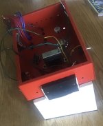
Interesting you should mention it, but I still have a keen interest in the 2018 the design for this project included just that, a 6V6 underneath the 2A3 specifically to keep the heat above the chassis.
However, it adds more heater power and current demand to the power trafo via the heater winding. It remains of intellectual interest but I’m not concerned about a cathode resistor in this project. Now, my chassis does have an Octal socket for the rectifier. If I went with a SS only rectifier, I could use that socket for a 6V6. Hmmmmmmmm?
However, it adds more heater power and current demand to the power trafo via the heater winding. It remains of intellectual interest but I’m not concerned about a cathode resistor in this project. Now, my chassis does have an Octal socket for the rectifier. If I went with a SS only rectifier, I could use that socket for a 6V6. Hmmmmmmmm?
Attachments
Member
Joined 2009
Paid Member

or a damper/rectifier diode under the 2a3 . Hmmmmmm? : ). . . . . . .I could use that socket for a 6V6. Hmmmmmmmm?
You could also look at Gary Pimm's archived page.Looked at a couple resources for vacuum tube-based CCS.
A Google search on "Gary Pimm Pentode CCS" also turns up a lot of stuff.
Member
Joined 2009
Paid Member

Member
Joined 2009
Paid Member
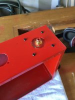
So, I've been thinking about that hot cathode resistor on the 2A3 and wondering if I can't mount the resistor above the chasis to keep the heat 'outside' ?
The issue is ensuring that the electrical connections are safe from prying fingers since one end of the resistor will be at a high voltage. Some of those enamelled power resistors have connectors on their sides that I could perhaps point down through holes in the chassis, add some heat-shrink tubing and they would be fairly inaccessible. hmmmmmm?

The issue is ensuring that the electrical connections are safe from prying fingers since one end of the resistor will be at a high voltage. Some of those enamelled power resistors have connectors on their sides that I could perhaps point down through holes in the chassis, add some heat-shrink tubing and they would be fairly inaccessible. hmmmmmm?

Member
Joined 2009
Paid Member
That could be a valid option, probably mount to a thick Al plate then bolt to underside so heat is spread out. Some folk don't like these metal clad resistors for tube amps - not sure the reasons why but just something I remember reading? The underside of the chassis is painted, not sure what kind of thermal resistance but with a thick Al plate and some thermal paste maybe that's a non issue. Not sure how well the chassis top surface will then shed the heat vs heating of the space underneath the chassis. I'm not sure this is much better than relying on holes and airflow with the traditional under-chassis resistor.
Maybe over-thinking - it's becomes moot if I avoid electrolytic capacitors as they are the most heat sensitive.
Maybe over-thinking - it's becomes moot if I avoid electrolytic capacitors as they are the most heat sensitive.
I would strongly suggest avoiding the aluminum housed resistors, as it can be rather difficult to understand their actual power ratings when they aren't mounted to a massive heatsink.What about using one of these fixed underside of top plate (or side panel) allowing the heat to be spread over a large area? Enough heat to discolour the paint?
Just wondering.
Ventilation counteracts heat soaking. Putting a resistor on the top side of the chassis that will have high voltage on one end isn't a great idea.
Member
Joined 2009
Paid Member
I think I'll follow your advice on this, and I've ordered a big fat green enamelled resistor that will begin life under the chassis - will see how that goes.
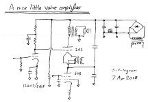
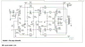
Part One of this project was published in the Volume 11, Number 2 Issue of Glass Audio magazine in May 1999. It describes a simple method of providing the very large grid drive voltage required by low mu vacuum power tubes such as the 6080/6AS7G family. The circuit appears to be fairly obvious but it seems no one had previously published anything like it.
The project also appeared in Electronics World. And from time to time here on DIY as further tests at various levels were run for THD & IMD,
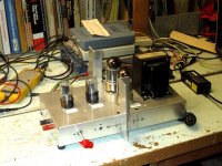
In later iterations I found the 6080 cathode resisters were not adequate. In the most recent last Spring the resisters are 5W each, heat sinked to the Aluminum chassis. But still needed large, external fins of some scrap Aluminum.
The project also appeared in Electronics World. And from time to time here on DIY as further tests at various levels were run for THD & IMD,
In later iterations I found the 6080 cathode resisters were not adequate. In the most recent last Spring the resisters are 5W each, heat sinked to the Aluminum chassis. But still needed large, external fins of some scrap Aluminum.
Attachments
Member
Joined 2009
Paid Member
Nice project! My v first tube amp build was a single ended 6AS7, which sounds much better than it has any right to. The cathode resistors do get toasty on that amp ! I think I brought that amp to Toronto once and you saw it but there was an issue somewhere and it was not able to play.
That bootstrapping off the UL winding of the OPT is a clever idea I have to say.
That bootstrapping off the UL winding of the OPT is a clever idea I have to say.


The amp is relatively simple, the 2x6080 are driven by a 2-stage Diff-Amp using 6SL7 & 6SN7.
All four cathodes of the 6080s have their own cathode resister & cap.
The Diff-Amp cathodes are returned thru resistors to -150V.
The OPT is based on a Hammond 1650N but at half the impedance, 2150 Ohms.
A special made for me by Hammond.
A few years after this piece in GA I fixed some spelling & grammar errors. And added more information.
The file is rather large to be stuffed here on DIY, anyone wants a copy of that PM me.
Attachments
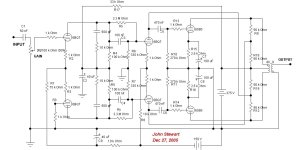
Yet another version of the boot strapped PP 6080 Amp. This one doesn't need an OPT with UL taps.
Not built in hardware but rather used Electronic Workbench (EWB) to run the simulation.
The 6BQ7s could just as well been 6SL7 & 6SN7.
The boot strap FB is 50% thru the 56K resisters across the OPT, proper phase.
Not built in hardware but rather used Electronic Workbench (EWB) to run the simulation.
The 6BQ7s could just as well been 6SL7 & 6SN7.
The boot strap FB is 50% thru the 56K resisters across the OPT, proper phase.
Attachments
I did quite a few other amps with a particular objective in mind. But this thread is about a 'Nice little Amp'.
After looking at a series of twin triode PP amps such as 6BX7, 6BL7, 6SN7 & 5998 there was an upper limit
of audio available while staying in the limits of dissipation.
The best of that series for a small amp were 6BX7 & 6BL7 at 3 Watts Audio while in Class A. The 5998 was 10W but no longer a small amp.
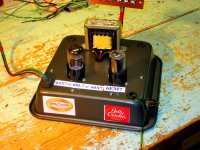
I called the amp The Betty Crocker Special, all used the same chassis an inverted Betty Crocker pie tin. Something I'd seen
in Joe Roberts magazine Sound Practices. Not recommended, I wouldn't do that again.
But a pair of 6EA7s would still work on that pie tin with major wiring changes. And where 12W dissipation total to make audio
was available the pair of 6EA7s could dissipate 22W. That translated to 7W of audio on a 260V PS while in Class A. The cathode tail
in the test rig goes to -150V, but any number of circuits are possible. All these tests are run from a lab PS.
The OPT is a Plain Jane Hammond 125E so that it was easy to get a good match.
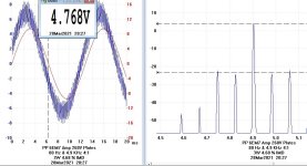
The Inter Mod test is unique. the frequencies used have a 3:4 relationship.
Something proposed by Graeme Cohen of Australia in 2008. It shows both THD & IMD products, 👍
After looking at a series of twin triode PP amps such as 6BX7, 6BL7, 6SN7 & 5998 there was an upper limit
of audio available while staying in the limits of dissipation.
The best of that series for a small amp were 6BX7 & 6BL7 at 3 Watts Audio while in Class A. The 5998 was 10W but no longer a small amp.
I called the amp The Betty Crocker Special, all used the same chassis an inverted Betty Crocker pie tin. Something I'd seen
in Joe Roberts magazine Sound Practices. Not recommended, I wouldn't do that again.
But a pair of 6EA7s would still work on that pie tin with major wiring changes. And where 12W dissipation total to make audio
was available the pair of 6EA7s could dissipate 22W. That translated to 7W of audio on a 260V PS while in Class A. The cathode tail
in the test rig goes to -150V, but any number of circuits are possible. All these tests are run from a lab PS.
The OPT is a Plain Jane Hammond 125E so that it was easy to get a good match.
The Inter Mod test is unique. the frequencies used have a 3:4 relationship.
Something proposed by Graeme Cohen of Australia in 2008. It shows both THD & IMD products, 👍
Attachments


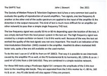
I used the SMPTE method to measure Intermodulation Distortion (IMD).
The note describes how that works. And how I apply it. The measurements
were made by a PicoTechnolgy 3224, 10 MHz, 2-Channel.
I used a Differential Probe in order to avoid ground loops.
The IMD side Bands are +/- 80 Hz & +/- 160 Hz from the 4.9 Hz signal.
And no PS side Bands at +/- 60 or 120 Hz, a good sign.
Some attachments here to help.
Attachments
- Home
- Amplifiers
- Tubes / Valves
- A nice little valve amplifier