If beta was irrelevant the bjt cascode would be ideal!
There's also the capacitances to consider, but you get the point about the beta, I hope. If beta was perfect, such as a fixed value of 100, then distortion would be purely linear, no harmonics. Again, disregarding the capacitances.
Here's not the case as TR2 act on the 2n3904/06
bases before TR3-Tr6 conveyor act on the emitters so the speed of switching is determined by the Tr3-Tr6 delay mainly and they are clearly slower than 2n3904/06. That sequence is deliberate to forcefully discharge the base of the trz that needs to shut off, the circuit doesn't rely only on the underbias for that matter .As with the capacitances involved Low cob trz are usually low on beta too because they are mainly destined for common base connections...in common base connection miller's capacitance is just a fraction of cob as the voltage gain is below 1X so cob or rather ccb in this case is irrelevant .
I remember that the
UHF-VHF amplifiers I was building in childhood to catch the russian's channels barely had 10db gain per 1 trz stage made with some BFR90...91 trz used in common emitter connection so its CCE would be important while multiplied with the stage voltage gain which was like 1/5 of the dc current gain thus 10 db gain was kinda big deal at 800Mhz .
BF422/423 would be a more natural choice than BFR trz which I'm not sure how stable can be in audio while bf422/3 definitely work in audio, but I'm pretty sure VHF trz can easily be toast due to very low CE max voltages common to these types of transistors.Unless you're going to use high power RF trz you won't get big VCE ranges...and big power trz are usually used in common base connection or cascoded "two on a die" to reduce the influence of their inherently higher cob ...
I modelled this amplifier using 2N3904 and 2N3906 transistors. In the original Blomley design the pairing was 2N3904 and 2N3905. There are some subtle differences in the specifications for the latter two devices. 2N3905 has lower minimum hFE than 2N3906 and lower fT. T on is the same for both but T off for 2N3905 is less than for 2N3906. If it takes marginally longer for this to turn of it will take marginally longer for it to turn on again. One might create a .model for 2N3905 and substitute the difference using 2N3906 as a template for the common performance parameters and run a new simulation, however Mouser have listed a 2N3905 made by Central Semiconductor that could be worth trying.
Since the choice has to align with 2N3904 which has a low hFE the datasheet for this would need to be checked to see which is the best match out of 2N3905 and 2N3906 - see attached.
Since the choice has to align with 2N3904 which has a low hFE the datasheet for this would need to be checked to see which is the best match out of 2N3905 and 2N3906 - see attached.
Attachments
Hisquare wave source
I picked up a trick from Ian that makes a better square wave source, ie no DC offset.
how do i properly connect the source? bypass the input bandpass filter? and what is the setting of voltage sources.
also is the variable f=10k the freq run?
Thanks!
You connect it same as you would a sine wave voltage. Filtering depends on what you are testing. Filtering is there to prevent a square wave from causing slew limiting so if you want to find the slew limit then yes, no filter. tr is the rise time which has to be >0. Vp is the peak voltage same as the spice sine wave spec. f is the frequency. The PWL (piece wise linear) formula is a series of line segments defined by the rise time, voltage and frequency. The problem with a normal pulse voltage is that it only has two states, the positive and negative peaks, so the initial simulation conditions are based on the negative peak and not zero. This creates a DC settling problem.Hi
how do i properly connect the source? bypass the input bandpass filter? and what is the setting of voltage sources.
also is the variable f=10k the freq run?
Thanks!

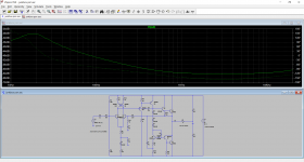
I made a quick run f=20k vp=0.6 (max input amplitude to avoid clipping)..well it is quick indeed. The resulting graph looks fine I think.
BTW the psu rail voltage sources is set to zero amplitude. Is this the correct setting?
Thanks again!

BTW the psu rail voltage sources is set to zero amplitude. Is this the correct setting?
Thanks again!
You can test for PSRR (Power Supply Rejection Ratio) by adding a non-zero amplitude and frequency etc to the DC rail voltages. Typically, that would be 100 or 120Hz as from a full wave rectifier PS, but you may be interested in channel crosstalk at other frequencies. You can also simulate a basic power supply with an AC voltage source + rectifiers and bulk storage cap. This can be very interesting simulating turn on transients and provides a more realistic supply noise. Note that a floating AC voltage can lead to simulation problems, not a problem if simulating a grounded center tapped transformer using two AC voltages.
Last edited:
Steveu Sir,
could you please share an .asc (spice file) for the PSRR method?
Thanks!
Sorry OP out of topic here.
could you please share an .asc (spice file) for the PSRR method?
Thanks!
Sorry OP out of topic here.
I don't do this often, but I would do it if I was going to build the circuit. So, I just grabbed an old schematic and added a "stimulus voltage" to the DC power supply and ran the AC analysis. Note that 24VDC power supply is also the AC analysis stimulus. Then plotting the output, we see how much of the power supply noise appears on the output, as a function of frequency, the PSRR.Steveu Sir,
could you please share an .asc (spice file) for the PSRR method?
Thanks!
Sorry OP out of topic here.
Attachments
A USB is a horrible source! In the first place it's digital and unless you use a 24-bit recording you get a sparkling sound, but deadly dull because the detail of the signal is lost in the quantization loss. It is also full of ICs and just a single simple op-amp (even a Burr-Brown audio one ) and you are full of intermodulation distortion. I tried this out because I thought a low-distortion op amp ( no less) would make a very good disk input RIAA curve. It does that well but the Blomley magic is gone. A single-transistor equalizer circuit works fine and such is the accuracy and quality that there is no need for treble and bass. I've tried hard - I made an op-amp balanced Blomley. When I made discrete-transistor op-amps, it sort-of worked but the hassle wasn't worth it. Peter Blomley is a designer in a million. Make his circuit - it has <1% distortion without any feedback at all.Hi Dermot,
thanks for the rave... I would be interested in running this amp fed by an USB interface which obviously is kind of an IC based pre-amp. Which measurable quantity would allow to judge, that the virtues of the Blomley amp are still being preserved, or would you exclude this right away?
Thanks for sharing your findings, Dermot ( @dherron )
We are also discussing a variation of Blomley's circuit here:
https://www.diyaudio.com/community/threads/the-magic-amplifier.376403/
We are also discussing a variation of Blomley's circuit here:
https://www.diyaudio.com/community/threads/the-magic-amplifier.376403/
Hello guys....
turns out, i have 2 transformers with single 44VAC secondary that could be perfect for this amplifier...
could someone confirm me that this amplifier can be used for powering 4ohm speakers?? seems like the original was intended for 15ohm speakers?!
...
thank you
turns out, i have 2 transformers with single 44VAC secondary that could be perfect for this amplifier...
could someone confirm me that this amplifier can be used for powering 4ohm speakers?? seems like the original was intended for 15ohm speakers?!
...
thank you
I'm going to say yes in practice because typically a 4 ohm speaker will have an impedance considerably higher than that over much of the audio band. If you are running it into a resistive test load then lower impedance will give higher distortion but then so do almost all amps. The 2200uF speaker coupling cap could perhaps be increased to 3300uF or even 4700uF to extend LF response into lower impedance loads.
Coupling cap is not a problem.... i was worried if it will be able to power my speakers that arr more then sensitive without blowing to pieces... this is because i have two identical transformers that have 44Vac secondary around and i hate to throw them away...... each of the transformers has 290VA. One is enough for stereo ... way to much but this seems like a nice project to hang around my F5 amplifier that is finally working now...
A load design for 15 Ohms would have 4 times less current draw than 4 Ohms. However, if you have an active sub, it may be OK, like for 5W of power. It will clip badly at 4 Ohms.
I thought about doing this project, I made PCB layouts for it, but gave up, as the design has been obsoleted long ago. May work OK with sine waves at low levels, but temp tracing of parts, IM, bias trimming, etc and normal playing with normal speakers left it in the dust. The more active devices in a circuit the more IM. Single tone measurements may be OK for the power utility company but not for music.
Nelson Pass had some ideas about this 2008
https://www.passlabs.com/technical_article/audio-distortion-and-feedback/
Experimenting and having fun building is part of the experience.
njahhh... i was really happy i found an amplifier that might use those two transformers with 44VAC single secondary i have around.....
....
ofh those that built Blomley, could anyone tell me what load they used for it.... 4 ohm, 8ohm, 16ohm???
thank you
....
ofh those that built Blomley, could anyone tell me what load they used for it.... 4 ohm, 8ohm, 16ohm???
thank you
@ egra or any other member.
Could you post a gerber file of the PCB Vers 2.1 board as shown in post #170 on the 30-03-2022 which was a Sprint file. JLCPCB does not read the .LAY files.
I would like to build this amp with newer transistors as mentioned in other posts in the thread,
Thanks in anticipation.
Gary.
Could you post a gerber file of the PCB Vers 2.1 board as shown in post #170 on the 30-03-2022 which was a Sprint file. JLCPCB does not read the .LAY files.
I would like to build this amp with newer transistors as mentioned in other posts in the thread,
Thanks in anticipation.
Gary.
https://www.pcbway.com/blog/help_center/How_to_generate_Gerber_from_Sprint_Layout_6_0.html
JLC takes zipped Gerber files.
You can generate/export Gerbers with above instructions with the design files and Sprint Layout.
The Demo version may accept the design size.
JLC takes zipped Gerber files.
You can generate/export Gerbers with above instructions with the design files and Sprint Layout.
The Demo version may accept the design size.
- Home
- Amplifiers
- Solid State
- The Blomley Class B amplifier