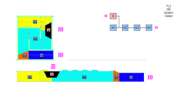
Not quite. BOXPLAN puts S2 at the driver's location, but it also allows the driver to be offset along the first fold (see image). S3 is used to make the end of the second fold. L34 is used for the transition around the corner to S4, and then L45 represents the rest of the path to the mouth.
Now is clear, the H1 and H2 are exactly the same between both models, but H3 and H4 are positioned in a different places. Boxplan allow different CSA for H3 and H4, while FreeCAD only for H4.
Excellent, thanks! Now, another question - how to separate one of the sides from the rest of the model, and export the whole thing in STL format? The competition requires that submissions be made in STL format.Attach you can find the T/S parameter I found for Peerless by Tymphany TC6FC00-04, Hornresp input .*txt file and also the 3D model I adjusted for you considering the external dimensions as you posted but internal ones are as closest as possible but not exactly the same due to model differences. Let me know if this is enough for you, otherwise I can customize it for you to precisely replicate your model.
External dimensions:
Height = 19,8cm
depth = 12cm
Width = 6,5cm
Total volume = 1,54L
Not quite. BOXPLAN puts S2 at the driver's location, but it also allows the driver to be offset along the first fold (see image). S3 is used to make the end of the second fold. L34 is used for the transition around the corner to S4, and then L45 represents the rest of the path to the mouth.
Just a small note.
If you check the sentence I wrote again, I was mentioning segments defined from Hornresp and they start with the letter H, see attachment. While you were mentioning cross section areas in your reply , S2, S3, S4 and lengths L34 and L45, those parameter are used to define segments. and in this sense FreeCAD work exactly the same way, the input D is the driver position and it defines the S2 placement as you shown.
The S2 is the mouth of H1 segment but throat of segment H2.
Looks like I mention the system model a bit often LOL.
Attachments
how to separate one of the sides from the rest of the model, and export the whole thing in STL format? The competition requires that submissions be made in STL format.
Didn't got your point, could you better indicate what is this side separation? I mean, you want to export individual panel? If this is the case I think you can just select the panel you want to export before clicking on export option.
I know that FreeCAD can export a format that can be imported from Google Sketchup, let me check if there is any indication or macro to export directly into STL, are you sure that other CAD formats are not accepted?
One of the two large external panels needs to be removable in order to make the box 3D printable. The side panel and the rest of the box can then be printed as separate parts, and then joined together after printed.Didn't got your point, could you better indicate what is this side separation? I mean, you want to export individual panel? If this is the case I think you can just select the panel you want to export before clicking on export option.
I know that FreeCAD can export a format that can be imported from Google Sketchup, let me check if there is any indication or macro to export directly into STL, are you sure that other CAD formats are not accepted?
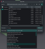
The notes for the competition state "Should be in .STL format if you can, other exported 3D model files should be fine like .dae. I cannot open .step or .smg, and I cannot open sketchup files newer than v17. V17 is free, runs on desktop and can export to .stl by the way, i recommend downloading it. If you cant export to .STL, then export to .dae. "
One of the two large external panels needs to be removable in order to make the box 3D printable. The side panel and the rest of the box can then be printed as separate parts, and then joined together after printed.
Try to export using DAE first as two pieces (1 side panel + the rest) and check importing from sketchup if it worked as you want.
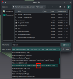
Yeah, I think I figured it out. I can just hold down the CTRL key and select all the parts I want to export, then select the Export option.
Thanks again!
Thanks again!
CTRL key
Welcome. Lets us know if you won the competition.
CTRL + A you select all, so it might be faster for you to remove one and add one by one.
You can also just select the bodies in the file tree using shift or ctrl like any file explorer.
LOL - I doubt I'd win. My money is on the Wicked Half for now, even though the design was mucked up a little.
But I'm counting on my design to produce a pretty high SPL down at Fb.
But I'm counting on my design to produce a pretty high SPL down at Fb.

The compression chamber is too big, but for car audio, you want a 60-65hz tune with a rising response in 2pi for music.Not really. After running the specs of the enclosures through Hornresp, they seem Ok, but some of the performance claims seem to be overblown. It was some time ago, and I lost interest.
Hi LORD and thank you very much for this great effort.
I'm playing with your sketches and experimenting with hornresp.....
Probably MKT plan need correction for the MKT-sketch.FCMacro file.
actual:
# Sketch change Values
App.ActiveDocument.Sketch.setDatum('thickness',App.Units.Quantity(str(18)+' mm'))
App.ActiveDocument.Sketch.setDatum('baffle',App.Units.Quantity(str(500)+' mm'))
App.ActiveDocument.Sketch.setDatum('D',App.Units.Quantity(str(220)+' mm'))
App.ActiveDocument.Sketch.setDatum('L1',App.Units.Quantity(str(400)+' mm'))
App.ActiveDocument.Sketch.setDatum('L2',App.Units.Quantity(str(100)+' mm'))
App.ActiveDocument.Sketch.setDatum('line1',App.Units.Quantity(str(80)+' mm'))
App.ActiveDocument.Sketch.setDatum('line2',App.Units.Quantity(str(120)+' mm'))
# Spreadsheet change Values
App.ActiveDocument.Spreadsheet.set('A7',str(550)+'mm') # Cab Int Width
# Rebuild Model
App.getDocument('BP6P').recompute()
corrected:
# Sketch change Values
App.ActiveDocument.Sketch.setDatum('thickness',App.Units.Quantity(str(18)+' mm'))
App.ActiveDocument.Sketch.setDatum('baffle',App.Units.Quantity(str(440)+' mm'))
App.ActiveDocument.Sketch.setDatum('D',App.Units.Quantity(str(220)+' mm'))
App.ActiveDocument.Sketch.setDatum('intangle',App.Units.Quantity(str(20)+' deg'))
App.ActiveDocument.Sketch.setDatum('extangle',App.Units.Quantity(str(36)+' deg'))
App.ActiveDocument.Sketch.setDatum('line',App.Units.Quantity(str(80)+' mm'))
App.ActiveDocument.Sketch.setDatum('L',App.Units.Quantity(str(300)+' mm'))
# Spreadsheet change Values
App.ActiveDocument.Spreadsheet.set('A7',str(600)+'mm') # Cab Int Width
# Rebuild Model
App.getDocument('MKT').recompute()
Something in TQWT-2 plan.
The TQWT-2-sketch.FCMacro need to add an input like this:
App.ActiveDocument.Sketch.setDatum('L4',App.Units.Quantity(str(76,50)+' mm'))
And in the TQWT-2-hornresp-nodialog.FCMacro this:

The second arrow is an add (for all plans no-dialog macro) to put the version of the hr record generated in its comment line.
The TQWT-2-sketch.FCMacro need to add an input like this:
App.ActiveDocument.Sketch.setDatum('L4',App.Units.Quantity(str(76,50)+' mm'))
And in the TQWT-2-hornresp-nodialog.FCMacro this:
The second arrow is an add (for all plans no-dialog macro) to put the version of the hr record generated in its comment line.
Hi LORD and thank you very much for this great effort.
I'm playing with your sketches and experimenting with hornresp.....
Ciao deepboy,
I hope you enjoy the tool, it's very useful to speed up simulations and more.
Thanks for your feedback and suggestion. The macro was fixed for those two issue models and also your suggestion to better track the simulation version adding simulation-number-generation on the "Hornresp comment" was also incorporated on those two models as well.
Cordiali saluti
Hi Lordsansui, I see you have focussed on bass cabinets. Could your approach be applied to designing a backloaded horn such as the Mauhorn or something generic?
Hi Lordsansui, I see you have focussed on bass cabinets. Could your approach be applied to designing a backloaded horn such as the Mauhorn or something generic?
Hi woodo,
It was easier an faster for me to make and release models using 12"/15"/18" drivers, while the major part are bass cabinets but not all of then are, like the Direct Radiatior models can be full range and others that are mode kick-bin.
The models MKT, Superscooper1 and Superscooper1 are backloaded horn and can be scaled to any driver size. While MKT present shorter horn length compared to superscooper1/s googling I saw that Mauhorn has longer length due to the amount of horn bends. If you want and if you can provide a good sketch I can find time to prepare this model for you.
This approach can be used to any loudspeaker design that can be simulated using Hornresp software. It's basically a CAD software with Parametric Sketch and Pyton Script to export hornresp inputdata. There are some videos in the webpage showing the benefits and how fast it can be whenever people needs to run too many simulations to optimize a particular design.
Attachments
- Home
- Loudspeakers
- Subwoofers
- Find here Parametric CAD files for loudspeakers plan - Hornresp integrated