That was quite an abundance of information all at once, and I must admit, it required a bit of patience to fully grasp. Having said that, I've taken my time to go through your message, and I believe I've managed to comprehend the essence of it. It's unfortunate that I've come across your insights after I've already completed the design, and it's likely that I've made some less-than-ideal choices in the process.Been out mowing my summer camp acreage. Sorry for the delay.
I have a common return to the drivers and output transistors, connected to speaker ground and power supply negative. I have a common return to the input transistor and VAS (the 2nd one). I connect those two to the output section through a small resistor, half or 1 ohm.
Here is where I buy bare Nema CE sheet. $16 for a 12"x24" piece. I drill as necessary, and use wires for point to point build. https://www.mcmaster.com/8491K7
My Apex AX6 has a single 69 v supply, produces 72 w into 8 ohms. Base AX6 has a 60 v supply for 50 watts. AX11 has a +-35 v split supply, with speaker connected to the center. Advantage of AX11, it has the constant current BC546 to give it some supply hum rejectioin. Disadvantage of the AX11, it has direct connected output transistors that, if you make a mistake like a bad solder joint, dump the entire supply current through the speaker coil. You can address this "problem" by buying a 7 to 12 part "DC on speaker protection" circuit. Most of these are snake oil, with a relay not designed to break big DC currents.
I handle the supply rejection problem of AX6 by regulating my supply, 72 v open circuit, regulated to 69 v with a series pass regulator on a separate board. Similar to the regulator built in to my dynaco ST120 chassis, but not relying on the limited gain of a 1967 2n3055 to regulate the supply current at the same time (which could not be replicated in 1985 when I bought the burned transistor ST120).
My AX6 would produce 24.3 vac on an 8 ohm speaker, for 5 seconds. That is 73 watt on 8 ohms. Same voltage out on 4 ohm speaker would be 147 watts. I don't believe a MJ15003 (which I have) would stand that current for very long.
100 w bulb series the AC line during test prevents faults from blow up parts so bad the TO3 tops bounce off the ceiling (I've done that). Slows down damage so you can probe with a meter and find out exactly what is wrong.
The parts you listed for the AX11 should work for the AX6. I think BD139/140 are little light duty for drivers, I use MJE15028/29 on my AX6 with heat sinks. TO3 output transistors are tough, but $10.50 each these days. MJL4281 are about as tough and $5 each, and only one hole to drill and get lined up, not three. 2sc5200 are as easy to mount but are not as tough as the On semi parts. I used MPS8099 as input transistor and the equivalent to MJE15028 as VAS. In a amp circuit, gain is set by the resistor ratios, most modern parts have high enough gain to meet the requirements Mike Slovatnic puts on them. On semi parts like MPS8099 (or MPSA06/56) are very high gain. I measured 300. Emitter followers like output transistors, gain is not important after the first generation parts like 2n3055 which had gain 5 at 3 amps ( horrible these days).
If you get your output bias idle current right with stacks of diodes, you can omit the bias setting pot. Pots are a reliability problem after years, the wiper oxidizes and loses contact. If you are off you can use a parallel resistor with the heat sink diode stack. Just the idle current is sensitive to what actual parts you use, no cookbook design is going to have right idle current for any combination of parts over the life of the part numbers. BTW I ended up with 2 1n4148 diodes and one shchottky diode (0.3 v drop) in the temperature sense position of the AX6. Clamped with a parallel pot, but if the pot opens up idle bias current creepts up to 40 ma, not too dangerous,.
Have fun.
(You certainly don't need to apologize)
As a non-windows user, I cannot run sims on this for you. First observation, Q5 is not doing anything. It is not a vbe multiplier unless the collector connects to something and spreads the voltage to two driver bases. Or two predriver bases.Could the configuration of these components under Minos effectively function? Considering potential alterations to resistor and capacitor values, has anyone undertaken the bold feat of integrating these intricate elements onto a sole circuit board?
The lower Q10 (of 2 Q10's) needs some sort of current limiter. No resistors.
No CCS on the input pair so no hum rejection as AX11 has. (Constant Current Source).
You haven't specified rail voltages. If you used +-25 v the 2sa1943/2sc5200 pair could handle about 2 amps by the AndrewT DC soa guide of full rail voltages. Could pump 150 w into 4 ohms at 25 vac swing, which is way more than the 2 amp soa allows (16 w). Better make sure it doesn't swing that far on output. Usually class AB amps can swing 1/2 the rail voltages if the gains are high enough. That is the reason 150 w honeybadger has 5 pairs of 2SA1943/2SC5200.
Others can further criticize the new design. I build old designs with a good reputation, or repair blown amps with good reputations. My 70 w/ch PA amp has two heatsinks 6 1/4" x 5 1/2" x 7/8". Layout of a 100 w board had best put the output transistors in contact with a heatsink as big. Or have a honking noisy fan on smaller ones.
Last edited:
Ltspice works fine under Wine and whatever the Mac equivalent is.As a non-windows user, I cannot run sims on this for you.
Ha Ha Ha Ha Ha Ha! Wine has never done anything but lock up the op system.Ltspice works fine under Wine and whatever the Mac equivalent is.
Than there must be something funny going on, I have been using it without any issues for years.Ha Ha Ha Ha Ha Ha! Wine has never done anything but lock up the op system.
(and I think I am not the only one)
The initial diagram intriguingly omits any resistors in proximity to said Transistor—an observation that piqued my interest. Could you kindly elucidate the optimal value and specific placement for such resistor? Should they be situated at the Collector, Base, or Emitter terminal?The lower Q10 (of 2 Q10's) needs some sort of current limiter. No resistors
I've been pondering over this for quite a few hours now, yet the grasp of how to implement the Constant Current Source (CCS) around Q1 and Q2 is still a puzzle to me.No CCS on the input pair so no hum rejection as AX11 has. (Constant Current Source).
You haven't specified rail voltages. If you used +-25 v the 2sa1943/2sc5200 pair could handle about 2 amps by the AndrewT DC soa guide of full rail voltages. Could pump 150 w into 4 ohms at 25 vac swing, which is way more than the 2 amp soa allows (16 w). Better make sure it doesn't swing that far on output. Usually class AB amps can swing 1/2 the rail voltages if the gains are high enough. That is the reason 150 w honeybadger has 5 pairs of 2SA1943/2SC5200.
Might a power supply rating of 35-0-35 be deemed slightly excessive in this context?
As a non-windows user, I cannot run sims on this for you.
I find myself on the cusp of returning to the Linux environment again. My patience with Microsoft is wearing thin, and I'm reaching a point where their offerings are becoming increasingly untenable. Although I've contemplated reverting to Linux Fedora, a setback emerged as my SSD ceased to function, leading me to the inevitable purchase of a new one. In the interim, I'm compelled to utilize an older HDD with Windows.
As for LT Spice, I made an earnest attempt to navigate its complexities, but regrettably, my efforts were met with frustration. The past few days have seen my patience wane as I grappled with a software sporting such an unwieldy GUI, leaving me feeling exasperated.
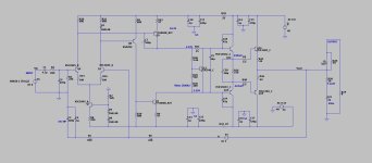
AX11 original schematic:
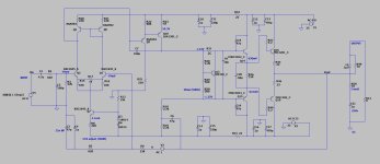
This represents my latest endeavor to fashion a schematic that radiates an enhanced and considerably more visually pleasing appearance:
With LTspice, the GUI is just really really awkward, not difficult.As for LT Spice, I made an earnest attempt to navigate its complexities, but regrettably, my efforts were met with frustration. The past few days have seen my patience wane as I grappled with a software sporting such an unwieldy GUI, leaving me feeling exasperated.
Once you're over that first initial bump it's not that bad.
Rebinding some shortcut keys really helped for me.
The original shortcut keys are just weird.
In the realm of endurance, there are those gifted with a vast wellspring of patience, allowing them to gracefully navigate through designs that may not be crafted with utmost refinement or intuitive ease. Regrettably, due to my circumstances, I stand among those who do not possess such boundless forbearance.With LTspice, the GUI is just really really awkward, not difficult.
Once you're over that first initial bump it's not that bad.
While I acknowledge that LT Spice may present challenges for newcomers, it appears that the software's creators—be they designers or engineers—may lack insight into the requirements of a simulator. This tool, which I believe holds particular relevance for a multitude of engineers or enthusiasts engaged in circuit experimentation, serves a not insignificant cohort.
Alas, I find myself conceding to a sense of defeat. The limits of my patience and energy have been reached, and the struggle to tame this enigmatic software has taken its toll. I find myself no longer capable of enduring this ordeal.
If perchance there exists an individual willing to lend their expertise in simulating this circuit, I would be profoundly grateful for such assistance. Alternatively, if one could direct me towards a more suitable software solution—one that might lead me to more fruitful outcomes—I would be immensely appreciative. Yes, I've ventured into the realm of TINA , my exploration into the realm of TINA software proved to be no different, as the outcomes I obtained remained consistent with my prior experiences with LT.
I humbly implore anyone listening to consider my plea. Your assistance would be a beacon of light in this challenging journey, and your support would be cherished beyond words.
I am afraid that most alternatives aren't much better (if not worse)Alternatively, if one could direct me towards a more suitable software solution
There is PSpice, Microcap or like you already mentioned TINA.
A nice intuitive GUI is definitely not of the strong points of MOST engineering software. Lol
That is probably even a huge understatement.
But yeah, I know the feeling, it can be so extremely frustrating at times.
I am sure there are plenty of people here to help you out! 🙂
You are right, AX11 doesn't have the resistors. I haven't built an AX11, I like speaker capacitors.The initial diagram intriguingly omits any resistors in proximity to said Transistor—an observation that piqued my interest. Could you kindly elucidate the optimal value and specific placement for such resistor? Should they be situated at the Collector, Base, or Emitter terminal?
The quad303 uses 10 ohms in the collector leg and 68 ohms in the emitter leg of driver Q106. Same driver position as Q9 in your revised schematic. I don't know why, but commercial amps on the market are subject to abuse like clipping and get warranty claims if they latch up to one power rail.
The simulator that ubuntu gives away is worth every penny I paid for it.
I tried the simulator that works off the browser, too. That one displayed currents that violated kirchoffs laws & scalar analysis with the calculator of the PC (or a hand calculator). I was simulating a RLC circuit in a passive crossover of a 2 way speaker. Bah!! humbug!
Your specification of a 4 ohm speaker puts enormous current loads on a single output transistor pair. My 70 w/ch Peavey M2600 has dual parallel output transistors. You might try putting heat sinks on the drivers and paralleling 2 or 3 pairs output transistors, which need to be matched for Vbe. Lower rail voltages get better current on the DC soa curve, which AndrewT told me predicted life of an output transistor. Again, MJL3281/4281 MJW3281/4281 NJW3281/4281 have more soa than a 2SC5200 (which is by definition a copy, Toshiba doesn't make them anymore).
Did you ever try searching for "image layout of AX11 amplifier" ? I got about 10 images from bing, some of which were stupid with the output transistors in the middle of the board (no room for heatsink) but some of which looked plausable.
Last edited:
Is it possible for me to incorporate output capacitors similar to those found in the AX6?AX11 doesn't have the resistors. I haven't built an AX11, I like speaker capacitors.
What is the 303?The quad303 uses 10 ohms in the collector leg and 68 ohms in the emitter leg of driver Q106
Reducing the voltage could prove advantageous as you mentioned? Would a configuration of 25-0-25 volts be sufficient for the intended purpose?Your specification of a 4 ohm speaker puts enormous current loads on a single output transistor pair.
Who's Andrew?which AndrewT told
Again, MJL3281/4281 MJW3281/4281 NJW3281/4281 have more soa than a 2SC5200 (which is by definition a copy, Toshiba doesn't make them anymore).
Despite recognizing the superiority of the transistors you mentioned, I'm opting to use the ones I got from a friend, hence my current choice.
I got about 10 images from bing, some of which were stupid with the output transistors in the middle of the board (no room for heatsink) but some of which looked plausable.
I'll be sure to avoid heading down that particular path, then.
Did you ever try searching for "image layout of AX11 amplifier" ?
Indeed, there is quite a multitude of options to choose from, which has made it challenging for me to determine the one that might yield superior results
with the speaker tied to the middle of a split power supply, a speaker capacitor would be subjected to negative voltage at half the cycle. Electrolytic capacitors cannot be subjected to negative voltage, except the non-polar kind. NP caps are expensive, about the biggest sold are 500 uf 100vnp for $10, and don't come with life ratings as compared with premium nichicon/rubicon/panasonic/vishay/kemet polarized caps. I buy 3000 hour service life caps up, to avoid replacing them after one years use. A 3000 uf 100 vnp electrolytic speaker cap would be $60. Forever life Polyprophylene 400 vac caps are about $74 for 200 uf, so for a 3300 uf speaker cap cost would be $1184 per channel. Cost from parts-express.comIs it possible for me to incorporate output capacitors similar to those found in the AX6?
The quad 303 was a very successful commercial single output transistor amp that sold tens of thousands of copies. Additional data, I managed to find the misfiled schematic for the Peavey M-2600 70 w/channel amp I own, the lower driver has a 47 ohm resistor from emitter to minus rail and no collector resistor to center.What is the 303?
Actually a single output transistor pair amp producing 25 vac into 4 ohms would produce 154 watts. V^2/R=PWould a configuration of 25-0-25 volts be sufficient for the intended purpose?
I^2*R=P for 154 watts gets output transistor current 6.2 amps. DC soa of 2sc5200 at 50 v is 4 amps. So no, following AndrewT dc soa rule for output transistors, single pair 2sa1943/2sc5200 is not safe at +-25 v.
AndrewT was a senior diyaudio forum poster, now deceased.
.
Last edited:
I acknowledge that AX6 boasts a notably more streamlined design compared to AX11, yet my commitment remains steadfast in bringing this project to fruition. If you share my inclination, you likely empathize with my imperative to concentrate. Presently, I'm taking a break from work and won't be returning to the computer. Perhaps in a couple of days, I'll reattempt the design with renewed vigor.
Could the incorporation of an additional speaker protection module potentially simplify matters? Would the speaker's position within the voltage swing still be maintained?
I'm considering testing the current configuration on a breadboard. Are there any potential risks or safety concerns I should be aware of before proceeding with the testing?
Your unwavering patience is greatly appreciated.
Most "DC protection" boards do the DC detection right, but use a cheap little hard contact relay with AC rated contacts to break the circuit. Arcs quench 60 times a second in an AC current, but just keep burning metal from one contact to the other with DC. Contacts can weld together. Read the DC protection threads for more experience.
There are DC protection circuits like Michael Bean's circuit that uses 2 NFETS and some opto coupled drivers to do the disconnection. Theoretically better than hard contacts, but I know of no commercial amp that uses this circuit.
I have enough trouble getting soldered joints to make contact on a Nema CE board when I build with wire. I had no good luck with push in breadboards in college physics lab, but the boards were worn and the wires were all cut 1" long or shorter. My push-in board sine wave generator didn't work either. Best of luck.
Another consideration of circuits outside a steel or aluminum case, they are subject to oscillation and interference caused by cell phone, police/fire/CB/ham/AM radio, etc. You have good filter on the input with 330 pf to ground (I use 180 pf on my AX6 to kill sports talk radio) but you don't have an 11 turn inductor parallel a 10 ohm resistor (5 to 10 watts) between the output and the speaker connector. The latter prevents interference from going back to the feedback transistor of the long tailed pair (q2) and being amplified. Of course you can't have a case on when you probe with a meter for faults. Again, clip lead on the meter negative to speaker ground, voltage probe with one hand.
I'll be offline myself as planning to go mowing again this end of week.
Last edited:
After a week of persevering through challenges, I have at last grasped the intricacies of LT Spice. Innumerable hours were dedicated to identifying components, comprehending datasheets, and procuring models. The culmination of my efforts materialized in the form of this achievement.
At this juncture, I find myself in need of the expertise present within this forum, seeking guidance on the realm of simulation. Regrettably, I stand with limited insight into the subsequent steps. Your assistance in illuminating the path forward would be immensely appreciated.
I extend my heartfelt gratitude in advance.
After dedicating several hours to initial simulations, I find myself encountering intriguing results that have prompted me to seek the insights of this esteemed forum. The situation I find myself in involves the collector voltages of two transistors, Q1 and Q2.
To my intrigue, the collector voltage of Q1 presents at 300mV, while Q2 manifests at a markedly different 34V. If memory serves, aren't both collectors meant to be harmoniously aligned in potential? In my setup, an input voltage of 0.5V is diligently provided. Yet, an uncertainty lingers—should this input voltage be judiciously adjusted to either lower or higher levels?
Additionally, I observe a rather substantial 5.03W power dissipation across R19. Could this, perchance, be attributed to a disparity in the proper biasing of the transistors? My scrutiny further unveils that a majority of PNP collectors are registering mere millivolt values on their collectors.
Seeking elucidation, I extend a cordial request to the astute minds of this community. Could you kindly illuminate the prevailing circumstances and suggest plausible explanations for this intriguing divergence? Your sagacious insights would be met with deep appreciation and gratitude.
In your sim post # 55 emitters of q1 & Q2 don't go anywhere. In ax11 schematic they go to collector of a ccs, a bc146. Get that straight, the middle of the schematic might settle down to 1/2 V+ - V-, and power in R19 might become normal.
Usually in sims people put a 1 vac input on the input, an 8 or 4 ohm resistor on the output, and sprinkle sim oscilloscopes and current meters at various interesting points. Higher gain circuits might like .5 vac on input . 1966 standard was 1.6 vac = maximum input, modern PA equipment seems to be +10 db or 0.48 volts or something.
Usually in sims people put a 1 vac input on the input, an 8 or 4 ohm resistor on the output, and sprinkle sim oscilloscopes and current meters at various interesting points. Higher gain circuits might like .5 vac on input . 1966 standard was 1.6 vac = maximum input, modern PA equipment seems to be +10 db or 0.48 volts or something.

here is a "gift" from another with spectrum disorders. (zip file).
I can't believe people build something like the AX-11 , it works .... but is quite non-linear.
I simmed it ... .2% THD - 330pF millers ??? What ?
The gift has 1/100th the distortion and uses accepted design "rules".
Just unzip the 2 files somewhere. LT will open it and just run !
I can't believe people build something like the AX-11 , it works .... but is quite non-linear.
I simmed it ... .2% THD - 330pF millers ??? What ?
The gift has 1/100th the distortion and uses accepted design "rules".
Just unzip the 2 files somewhere. LT will open it and just run !
Attachments
I had indeed observed all those aspects prior to your response, subsequent to a meticulous comparative analysis of the two schematics. However, what truly perturbs my equanimity is the realm of simulation. Regrettably, my knowledge in this domain is quite lacking, and curiously, the more I delve into its intricacies, the more it becomes enshrouded in a veil of perplexity. 🙁In your sim post # 55 emitters of q1 & Q2 don't go anywhere. In ax11 schematic they go to collector of a ccs, a bc146. Get that straight, the middle of the schematic might settle down to 1/2 V+ - V-, and power in R19 might become normal.
To be more specific, in the AX11 schematic, a wire from emitters of q1 & q2 goes to collector of Q3, the CCS. There is no dot at the crossing with the ground (center tap of transformer) which means no connection. In the simulation you have connected the collector of Q3 to the "ground", the center tap of transformer. Q1 and Q2 emitters are not connected to anything.
There are tutorials on simulations on the "design & build" category of diyaudio forums, called "software tools" forum. After reading one or more of those, you might post your corrected simulation over there and ask for criticism+help. I don't see any oscilloscope symbols, sine wave generator symbols, or ammeter symbols on your sim plot, which are usual symbols I see on sims all the time. Not running windows, I can't use it myself, but will look at the results from time to time.
As wg-ski pointed out, long tailed pair amps (Q1 & Q2) in sim have perfectly matched transistors. In real life they are usually not and the mismatch of gain or vbe of those can affect enter voltage and distortion profoundly. Big amp manufacturers buy parts in lots of 10000 and can specify how much match they want in that lot for a price. You, the individual, get whatever transistors were left in the bin at a distributor after the big guys bought a couple of hundred.
In quibbles about Ostrippers simple amp, drivers MJE15032/32 I would substitute with MJE15028/29 since they have less Cob and might be a little faster. VAS 2sa1381 has been sold by digikey in the past, but they didn't know at 7AM EDT of any in stock at any manufacturer whose inventory they link to. They don't have any. The "2sa1381" digikey bought most recently is in a TO220 pcakage (from ON), not a TO126 package like all the other suppliers.
I agree with ostripper on the 47 pf capacitors on the cb jiuntion of the drivers instead of 330 pf. My original ST120 board had 51 pf capacitors there after bad experience caused them to issue a service bulliten with changes. . Performs well after the stupid dynaco idle bias control circuit is changed to provide 20 ma bias on the output transistors even cold & soft.
Last edited:
- Home
- Amplifiers
- Solid State
- AX11 Building - Dealing with both electronics and autism