Wow that looks amazing 🤩. Your white beach color looks amazing. I like it a lot and no it doesn’t remind of anything but beach sand. I think it goes well with the black gloss finish on the top tear drop cabinet. You have done a amazing Great Job with making the speaker cabinets.👍. I wish you lived near me? All my wood shops and help are retired or older now and don’t want to help me. I get it. We’ll take care of your self. Jeff
long time no see but continued and got some visible progress 😀
after I did base layer you saw on previous page, I saned it again and put another thin coat on it. Some defects were still visible so I filled those with very fine filler, sanded again...


after that I applied another thin coat and top layer - black gloss applied by foam roller. This resulted as expected with "structured" surface. I had mixed feelings about black but then tried to fit into interior and white ones would be too much to handle visually at my place = I have oak audio shelf + very light floor and needed it to blend in somehow and black was the best for this. To ease up the glossiness of structured surface I put another 2 coats of semi matt polyurethane water coat over that. This very nicely softened surface and improves durability of the finish:


Finally as boxes were ready I glued in bass ports with epoxy and filled all cabinets with 4,5cm thick audio foam. It was unbelievable how much it "eated" the whole 1m x 0,5m piece just dissapeared in 😀


As everything was ready I wired all the wires. To prevent rattle I've coated them with self-adhesive foam seal whenever was possible. Also the teardrop contains 2,5cm foam on the walls (it was very tricky to cut the right shape for this 😀 ) + synthetic wool in the middle. Not too much stuffed, but enough and so its no problem to mount the speaker in... and ohh also other speakers...


As mounting rim of the Hivi L6 is very uggly I have printed very precise piece that sticks just right on the edge of the rim. It also creates very nice visual connection between the speaker rubber and teardrop so it blends in and hide the screws. Extra rim piece looked very nice as is from 3d printer so no painting was required, I think it just adds visually, see for yourself:

As the speakers were all wired I had to mount the boxes on plinths. (yes the bottom bass speaker had to be removed to do this) To secure screws apropriately I've used angled pads below the nuts, all stainless steel M8 screws for added strength ofc 😀

ohh and before final mount I've treated concrete surface of the plinths by water polyurethane varnish - glossy one this time. It went very well, also before applying it I watered concrete so it had better chance to soak in to the concrete. I did two layers. Overal, it looks nice and adds very good protection against basic home dirt:


everything was ready to put things together. All heavy stuff = a lot of sweat, but the result well worth it!

btw it weights over 50kg now 😀
All ready for measurements, and as I cannot insert more images into one post here, I will continue with the next one...
after I did base layer you saw on previous page, I saned it again and put another thin coat on it. Some defects were still visible so I filled those with very fine filler, sanded again...
after that I applied another thin coat and top layer - black gloss applied by foam roller. This resulted as expected with "structured" surface. I had mixed feelings about black but then tried to fit into interior and white ones would be too much to handle visually at my place = I have oak audio shelf + very light floor and needed it to blend in somehow and black was the best for this. To ease up the glossiness of structured surface I put another 2 coats of semi matt polyurethane water coat over that. This very nicely softened surface and improves durability of the finish:
Finally as boxes were ready I glued in bass ports with epoxy and filled all cabinets with 4,5cm thick audio foam. It was unbelievable how much it "eated" the whole 1m x 0,5m piece just dissapeared in 😀
As everything was ready I wired all the wires. To prevent rattle I've coated them with self-adhesive foam seal whenever was possible. Also the teardrop contains 2,5cm foam on the walls (it was very tricky to cut the right shape for this 😀 ) + synthetic wool in the middle. Not too much stuffed, but enough and so its no problem to mount the speaker in... and ohh also other speakers...
As mounting rim of the Hivi L6 is very uggly I have printed very precise piece that sticks just right on the edge of the rim. It also creates very nice visual connection between the speaker rubber and teardrop so it blends in and hide the screws. Extra rim piece looked very nice as is from 3d printer so no painting was required, I think it just adds visually, see for yourself:
As the speakers were all wired I had to mount the boxes on plinths. (yes the bottom bass speaker had to be removed to do this) To secure screws apropriately I've used angled pads below the nuts, all stainless steel M8 screws for added strength ofc 😀
ohh and before final mount I've treated concrete surface of the plinths by water polyurethane varnish - glossy one this time. It went very well, also before applying it I watered concrete so it had better chance to soak in to the concrete. I did two layers. Overal, it looks nice and adds very good protection against basic home dirt:
everything was ready to put things together. All heavy stuff = a lot of sweat, but the result well worth it!
btw it weights over 50kg now 😀
All ready for measurements, and as I cannot insert more images into one post here, I will continue with the next one...

Below a few measures by umik1...
impedance plot of the woofers to check for the port tuning:

If I remember correctly I measured this one with box elevated - sitting on some polystyrene pads as wires where sticking out of the bottom. After mounted on plinths it was closer to the "ground" and this somehow prolonged bass port and lowered the tuning even further to 28,5Hz 🎉
frequency plot of woofers = 1m farfield + nearfield with bafflestep compensation + nearfield port resized to match Sd of the woofers (-7dB):

To check resonance of midbass here is imp plot:

and frequency response, again 1m farfield connected to nearfield and bafflestepped. Angles 0°/15°/30°/45°

frequency response of the tweeter, 0°/15°/30°/45°

I did measure 0-15-30-45-60-75-90 angles and wanted to design crossover in virtuixcad, but the design was very tricky and phase looked strange and so I was advised to use different style of measurement. For all these ^^ I've used umik1 with acoustic timing reference, which worked for frequency plots, but appeared it does not work very well for phase measurement. I used tweeter for timing reference and tried to measure rest from the same position but it just didnt work very precisely...
so I bought XLR calibrated mic and did all measures of all angles again with loopback as timing reference. Finally phase was very correct from the first sight. It was so precise I was able(must) to apply same windows and time shifts for impulse response and it started to shape up.
To not ruin my phase plots I have not connected woofers plots with nearfield and used only farfield measures for the crossover design. I am limited by about 220-250hz range but still ok to check the phase with midbass I think.
Now I am playing in virtuix and trying to design crossover but its VERY tricky. As you can imagine no baffle does it's thing and match phases correctly looks like impossible task. When I match it on lets say reference angle of 30 degree, it splits up elsewhere and vice versa. When I have nice dispersion I lose phase. Its going in circle for me atm but its been a couple of days I am still trying...
just in case someone would be interested to play what it does, here are the measurement files available for download:
https://uloz.to/file/nLBBLCwZFg0Y/m...2A2MyA2AwLwMxBGL3AzD5MIxjM0M5IHguDJq3DzAuBN==
some of my attempts so far are below... not sure which way I should incline to so I welcome any advices 😀 Its not going to be hi-end, I know that from beginig. I am just trying to do the best possible from what I've got.


impedance plot of the woofers to check for the port tuning:
If I remember correctly I measured this one with box elevated - sitting on some polystyrene pads as wires where sticking out of the bottom. After mounted on plinths it was closer to the "ground" and this somehow prolonged bass port and lowered the tuning even further to 28,5Hz 🎉
frequency plot of woofers = 1m farfield + nearfield with bafflestep compensation + nearfield port resized to match Sd of the woofers (-7dB):
To check resonance of midbass here is imp plot:
and frequency response, again 1m farfield connected to nearfield and bafflestepped. Angles 0°/15°/30°/45°
frequency response of the tweeter, 0°/15°/30°/45°
I did measure 0-15-30-45-60-75-90 angles and wanted to design crossover in virtuixcad, but the design was very tricky and phase looked strange and so I was advised to use different style of measurement. For all these ^^ I've used umik1 with acoustic timing reference, which worked for frequency plots, but appeared it does not work very well for phase measurement. I used tweeter for timing reference and tried to measure rest from the same position but it just didnt work very precisely...
so I bought XLR calibrated mic and did all measures of all angles again with loopback as timing reference. Finally phase was very correct from the first sight. It was so precise I was able(must) to apply same windows and time shifts for impulse response and it started to shape up.
To not ruin my phase plots I have not connected woofers plots with nearfield and used only farfield measures for the crossover design. I am limited by about 220-250hz range but still ok to check the phase with midbass I think.
Now I am playing in virtuix and trying to design crossover but its VERY tricky. As you can imagine no baffle does it's thing and match phases correctly looks like impossible task. When I match it on lets say reference angle of 30 degree, it splits up elsewhere and vice versa. When I have nice dispersion I lose phase. Its going in circle for me atm but its been a couple of days I am still trying...
just in case someone would be interested to play what it does, here are the measurement files available for download:
https://uloz.to/file/nLBBLCwZFg0Y/m...2A2MyA2AwLwMxBGL3AzD5MIxjM0M5IHguDJq3DzAuBN==
some of my attempts so far are below... not sure which way I should incline to so I welcome any advices 😀 Its not going to be hi-end, I know that from beginig. I am just trying to do the best possible from what I've got.
Last edited:
Now the challenge, I feel, is with the unbaffled/bullet dome tweeter.
Although it’s good at creating wide dispersion in the top octave 10-20Khz; it also makes the tweeter near omnidirectional around 2KHz.
The very experienced @Pida , who valiantly reworked the B&W 802D, achieved this-
https://pkaudio.webnode.cz/bw802d2/
So thank you for posting your project files.
VituixCAD2 pixel starers like myself @fluid @vineethkumar01 and @hifijim will certainly be tempted to take a look and assist (?persist)
Hopefully we can get a balance of amplitude response, phase response, directivity matching.
Whilst prototyping, do you have a DSP setup where you can switch between multiple crossovers and audition?
We could probably fine tune a better response with a DSP based crossover if you did.
Otherwise you will plan to build various crossovers, or settle on one and fine tune later?
Now back to your passive crossovers this far
A) In case I missed this in previous posts; I take it you measured each and every driver on its own axis; as per VituixCAD user manual?
Eg.
https://kimmosaunisto.net/Software/VituixCAD/VituixCAD_Measurement_ARTA.pdf
If you did, please set to set your reference axis in the Y plane- eg. If you want your tweeter to be “on-axis” the. Tweeter is 0mm, then set mid - c mm; woofers -d mm, c and d being the actual distance between the tweeter and mid and centre of 2 woofers respectively.
Of course you can set the mid at 0mm; if it closer to your ear height at seat listening level, in which case the tweeter is + mm, woofer is - mm.
B) consider use of acoustic LR2 crossover for your MF/HF for better directivity matching.
Last edited:
tktran303 thank you, no I do not have any dsp and wanted to go passive way, build one prototype, measure/tweak etc…
I was in contact with Pida and he adviced measuring all speakers on their particular axis as you mentioned. I didnt do that, yet, as that would be serious problem for me to lift speaker so high to measure woofers without reflections.
I’ve measured all from one static position 1 meter away at height of tweeter with same t=0 position for all measurements. I was affraid of phase mismatch moving mic here and there for different drivers and going back where i messed phase with umik.
all farfields are linked in post #44 just in case someone wants to take a look below are downloadable raw .mdat files of that. I think directly impulses could be imported to virtuix probably somehow (I havent figured that one yet). Included you can find also nearfields which could be connected directly in virtuixcad probably(another thing I havent tried yet because affraid of phase mismatching).
Beware of nearfields as those phases are probably off so thats why I was not connecting it to farfields in my last try but maybe there is a way how to align it also phase-wise 🤔
https://uloz.to/file/XDdjmBIVa3Op/extras-zip#!ZGLjAQR2AGOvATWuZzR0AGZ0BGAvBUOCZ2SQGJ9+MyxmEJVjZj==
Beware of nearfields as those phases are probably off so thats why I was not connecting it to farfields in my last try but maybe there is a way how to align it also phase-wise 🤔
https://uloz.to/file/XDdjmBIVa3Op/extras-zip#!ZGLjAQR2AGOvATWuZzR0AGZ0BGAvBUOCZ2SQGJ9+MyxmEJVjZj==
today I've figured out how to use merger in virtuix and must say its 10x easier than in rew 😀 so tried merge neafields of woofers with ports applied bafflesteps and port attenuated based on sd. Also connecting phase response was more clear and easier, not sure I did everyting 100% but looks good. Tried to play with crossover but no significat progress so far. Looks like I have 2 ways I can go. Sharp filter on tweeter and split mid completely but directivity suffers.
Or I can let midbass scream to the heavens as much as he can to somehow meet the tweeter on his way up, a bit hell idea but here it is, I think directivity looks better. Not sure its worth it, maybe i'll have to test both styles and will see which one is better

Or I can let midbass scream to the heavens as much as he can to somehow meet the tweeter on his way up, a bit hell idea but here it is, I think directivity looks better. Not sure its worth it, maybe i'll have to test both styles and will see which one is better
Last edited:
looking better in terms of on and off axis. can you show the listening window?
Consider increasing the Y scale so your view in 25dB. Also, considering padding tweeter down another dB
Consider increasing the Y scale so your view in 25dB. Also, considering padding tweeter down another dB
I think I did something wrong when connecting nearfields, second attempt shows better low end response... maybe, not sure, maybe same... anyways below with listening window

stupid question but what is it good for? 😀 I hope I get it rightConsider increasing the Y scale so your view in 25dB.
Last edited:
tried to shift tweeter a lil bit higher + ironed the bump... I think thats the one I'll try for first tests.
(Cannot do anything about 10k holes as there is phase splitting up with tweeter, if I fix it with RL on mid it splits 0 axis on 6k what sux more than that 10k on 90...)

(Cannot do anything about 10k holes as there is phase splitting up with tweeter, if I fix it with RL on mid it splits 0 axis on 6k what sux more than that 10k on 90...)
Try adding Zobels especially to the mid, it has a strange filter shape. With a closer look I don't think have a low pass on the mid at all, 56 mfd capacitors and a 1.5mH inductor seem way too large.
After month of simulations I built several prototypes... tried version where tweeter went quite low and midrange high and that wasn't very good (the one above slightly tuned) as it contained all mid resonances and also the tweeter "soft" resonance. The dispersion was nice however it was anoying to listen to and contained too much energy in high mids/low hights - not good.
Then I tried one, properly crossed over while cutting mid and tweeter resonances completely off. A bit tradeoff as I had to cross higher and steep nearly at 4k so dispersion suffered a little bit but it sounds incredibly well balanced. Proprobably this is going to be the "final one"... - still playing with low cross point but thats only about changing values here or there. All is tuned for slightly decreasing 30 degree as reference axis, but to see all well there is zero choosen in the graph below:

already designed PCBs and they're on the way... I found out the 6,8mH inductors are very heavy and PCB would not be able to handle that, so thats why there is a cutout and I will glue it directly to concrete.

also still waiting for a few proper value inductors so hopefully next month all will be finished 🙂
My first impressions from listening the "good" prototype (one speaker only):
It sounds very different then one would expect from first look. I would expect boomy bass or something like that, but on contrary. Very detailed and clear sound, I am amazed and very satisfied. I am looking forward to try both speakers and try proper stereo, that will be something! Couple of points for further description below:
Geoff Castellucci - Sixteen Tons = for testing bass balance of boomy speakers. Very well played, there wasnt anything like too much nor lack of, awesome! but not as tricky as the one below...
Sara K. - I can't stand the rain = classic I know very well. Guitar + details around can be tricky but all was well. Mids are okay, nothing that would annoy me even for very long listening, very nautral and "live". Now it comes... I think I have heard for very first time the low kick drum as it is supposed to. I figured out I have never ever heard it - not even thru my audiophile headphones. Its incredible ultra loooow experience 😳
To test depths even further well ofc I could try some sub testing tracks but those sucks and I wanted something I know well. So I tried Hanz Zimmer - Why so serious used in movie The Dark Knight (batman) especially ~3min part, I remember hearing this on live concert. Well "hear" as there was mostly just metal parts of the hall shaking. I have no words how to describe this... girfriend just looked at me and started to laught 🤣
Then I tried one, properly crossed over while cutting mid and tweeter resonances completely off. A bit tradeoff as I had to cross higher and steep nearly at 4k so dispersion suffered a little bit but it sounds incredibly well balanced. Proprobably this is going to be the "final one"... - still playing with low cross point but thats only about changing values here or there. All is tuned for slightly decreasing 30 degree as reference axis, but to see all well there is zero choosen in the graph below:
already designed PCBs and they're on the way... I found out the 6,8mH inductors are very heavy and PCB would not be able to handle that, so thats why there is a cutout and I will glue it directly to concrete.
also still waiting for a few proper value inductors so hopefully next month all will be finished 🙂
My first impressions from listening the "good" prototype (one speaker only):
It sounds very different then one would expect from first look. I would expect boomy bass or something like that, but on contrary. Very detailed and clear sound, I am amazed and very satisfied. I am looking forward to try both speakers and try proper stereo, that will be something! Couple of points for further description below:
- very clear and detailed mids
- tweeter kind of okay. I am not an audiophile that can recognise pricey ones from cheapo stuff, but there is nothing annoying, there is nothing too much nor lack of, so I suppose "ok". Despite textile dome I am surprised how nice even metal instruments are played.
- bass ... oh my! In past I had many speakers, even the ones which can go VERY low (lab 12 sub and such), but never ever this clear and how to describe... "easy" low. It is very impressive bass experience to listen to it. It is not overbassed in any way, sometimes I would say maybe there could be more, but no, thats it and right - its not boomy, its exactly as needed and very finely detailed. Where it needs to go low it seems there is no bottom. I have never experienced shuch a clear and deep bass so well balanced to the amount of midrange. I have heard lowest bass in my life I wouldn't believe is possible to hear. What is surprising even on low listening levels its very balanced. Usually speakers need more drive to open up properly but not this... does't matter how quiet or loud it plays it still keeps the balance.
- low sensitivity + 8 ohms = it wants power! well... voltage 😀
Geoff Castellucci - Sixteen Tons = for testing bass balance of boomy speakers. Very well played, there wasnt anything like too much nor lack of, awesome! but not as tricky as the one below...
Sara K. - I can't stand the rain = classic I know very well. Guitar + details around can be tricky but all was well. Mids are okay, nothing that would annoy me even for very long listening, very nautral and "live". Now it comes... I think I have heard for very first time the low kick drum as it is supposed to. I figured out I have never ever heard it - not even thru my audiophile headphones. Its incredible ultra loooow experience 😳
To test depths even further well ofc I could try some sub testing tracks but those sucks and I wanted something I know well. So I tried Hanz Zimmer - Why so serious used in movie The Dark Knight (batman) especially ~3min part, I remember hearing this on live concert. Well "hear" as there was mostly just metal parts of the hall shaking. I have no words how to describe this... girfriend just looked at me and started to laught 🤣
The new crossover looks vastly superior to your previous attempts. You filter shapes still look a little strange. I would try a Zobel on the mid, you might find that you can leave out the notch filter with listening tests. I would try the same on the tweeter.
zobel will just free up the highs and can not handle the 3k specific peak the midrange suffers
what specific do you mean? everything has a reason and specific purpose where isYou filter shapes still look a little strange
In my experience the band pass filter on the mid range of a 3 way crossover is the trickiest part, the low pass and high pass sections cause some very strange interactions. By adding a Zobel on the mid range I have been able to achieve near textbook acoustic slopes which then allow for smooth a transition to the woofer and tweeter. I will then adjust the values of the Zobel, low pass, high pass and padding resistors to match a target slope in VituixCAD.
My recommendation to try listening tests with and without the notch filters also come from experience, if you can get the low pass on the mid range to 24db/octave there is a good change that you will not hear the distortion from cone breakup. Looking at the HiVi frequency response I don't see any problem that would require a notch. The bump at 5kHz on the mid looks to me to be caused by the crossover and doesn't show in the manufactures data.
Nice work, beautiful cabinet, I'm sure you will end up with something special.
Attachments
Finally gathered all components needed and finished my crossovers. I've glued bass coil directly to the concrete with 5 minute epoxy. For PCB standoffs I used 3mm plastic washers and instead of standard screws I used metal M4 threaded stands. These stands are exactly as high as the cavity in concrete so it will provide securing point for bottom cover. Not sure what cover yet but I think some very thin plywood with foam seal will work fine.

For connection on the back I used standard "ebay" chinese beefy terminals, 4 of them so I can bi-amp bass and mid/hi section separately if want to. My plan was to cut copper bar connection pieces and use normal connection to my diy mc452, however I have also mc275 so still thinking about biamping the bass section as solidstate and mid/hi with tubes. Will test later on and see if there is some difference... 🤔

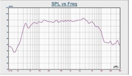
Below are my final measurements by umik for angles 0° - 90° I am amazed how well it matches the simulation at least the high part...
Its very tricky to measure this indoor as my low/mid xover frequency is 300Hz and thats exactly the point when I start to receive first reflections. Also because of this its unreal for me to combine bass nearfield to this as bass part is xovered too... so below graph for ~300+

my "reference" 30° angle only:

Impedance graph // 4,6R minimum:

For comparison, simulation is a few posts above, if you notice a few dB difference in high part thats my old umik misscalibration. Simulation was measured by freshly calibrated sonarworks xlr mic.
For connection on the back I used standard "ebay" chinese beefy terminals, 4 of them so I can bi-amp bass and mid/hi section separately if want to. My plan was to cut copper bar connection pieces and use normal connection to my diy mc452, however I have also mc275 so still thinking about biamping the bass section as solidstate and mid/hi with tubes. Will test later on and see if there is some difference... 🤔
Below are my final measurements by umik for angles 0° - 90° I am amazed how well it matches the simulation at least the high part...
Its very tricky to measure this indoor as my low/mid xover frequency is 300Hz and thats exactly the point when I start to receive first reflections. Also because of this its unreal for me to combine bass nearfield to this as bass part is xovered too... so below graph for ~300+
my "reference" 30° angle only:
Impedance graph // 4,6R minimum:
For comparison, simulation is a few posts above, if you notice a few dB difference in high part thats my old umik misscalibration. Simulation was measured by freshly calibrated sonarworks xlr mic.
Last edited:
- Home
- Loudspeakers
- Multi-Way
- 802 Diy speakers