
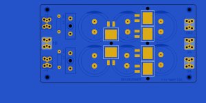
OK , as well as finishing the mini OPS BOM , I'll make the power board "deluxe" !
Fuses + 2 D2PAC mosfets and 4 - 30A/200V D2PAC's - https://www.mouser.com/ProductDetail/STMicroelectronics/STTH3002G-TR?qs=%2BFmDY/mH7IYAbQjpkMD%2BEQ==
"monster rectifiers" and the IPB025N-10N3 G MOSFET's under the PCB , can be heatsinked right to the chassis.
- 3 X 6800uf - 20Kuf + per rail ....will power the stereo pair of "mini" or the big arcwelder.
- infinite chassis heatsink. 30A is overkill. Might not even need to be sinked with "normal" use - but , why not ?
- and integrated rail switches. I'll make them bridge-able if they are not wanted or needed.
Those rectifiers are cheap ($2) and would be easy to solder. Yeah , a hybrid TH/SMD design makes full use of a double sided PCB.
Any ideas on what connector to use for the protection , and do we need (rail sense) for the MCU ? I might as well add the opto
as a 8 pin SMD as well (underside, as well). Those ($7) MOSFETS are freakin' expensive , could a cheaper one ($1.88)- https://www.mouser.com/ProductDetail/Infineon-Technologies/IPD60N10S4L-12?qs=LxJ0xX/WJR62JocYo2s6bA== be used ?
PS - I see the protection circuit has a display .... what does it display ?
OS
Attachments
I'm not sure how you would connect those rectifiers to the chassis for heat sinking. The dump their heat through the back plate into the copper. There are solder on heat sinks available for these but they're at whatever potential the cathode is at. TO220 rectifiers work well for chassis sinking but all the screws make them a paint for service.
I never bothered with rail sense on the supplies. We're doing pretty much the same thing in the output stage of the amp already. Sense resistors add unneeded supply sag (just like CRC supplies) and hall effect sensors can get expensive quick and hog real estate.
Those mosfets would likely be fine for rails. It's tough to pick out a certain mosfet as they seem to go out of stock everywhere as soon as you find one you like. Prices are shooting up fast too.
With the display I offloaded the temperature sensing to the display CPU and added an alarm output to signal the control board of an overheat condition. The display would tell you whatever state the control board was in (soft-start, supply on, speakers on, ...) as they changed. While the amp was on it would display temperatures of each channel. When the amp was shut off it would display time info. It's pretty easy to make them display whatever you like these days.
You mean "PITA" ... not "paint" he he. Yes , I thought about sinking off the tops of those D2PAC's - nope.
Next best bet is the 20A "GBJ" package - https://www.diodes.com/assets/Datasheets/ds21220.pdf
That will only take one hole through the board for the sink.
Is a common MOSFET like this IRFB4620 good enough ? https://www.mouser.com/datasheet/2/196/Infineon_IRFB4620_DataSheet_v01_01_EN-3166260.pdf
25A/200V - TO-220. I still might have to SMD the opto (underneath a supply cap). But the opto is a big dip-8 SMD ... easy.
Good , back to nearly all through-hole. Plenty of SMD for control boards and IPS's.
OS
Attachments
IRFB4620 would likely work fine, but the RDSon is getting pretty high. Might start to cause supply sagging.
Target - RDSon ?IRFB4620 would likely work fine, but the RDSon is getting pretty high. Might start to cause supply sagging.
I was about to give up on TH MOSFET's until -https://www.mouser.com/ProductDetail/Diodes-Incorporated/DMTH10H005LCT?qs=5666Nh5RPmYDiApfkPHvLg== real low RDSon. 100V/100A... $2.50 !
OS
OS
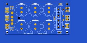
Yes ,5 ! here is the finished layout with those TH mosfets plus the dip-8 smd opto. Semi's are all 15A+ traces (some double-sided 7.5A).I always try to stay under 10. Those ones look better!
Turned out nice , it's no longer a "mini" - needs to be renamed. 63V can be 6 X 10K (30mm X 50mm) , 80V = 42Kuf , 100V = 30K+.
Attachments
Looking at the control board circuit ... You have some I/0 directly controlled by the ATmega , other functions ported through I2C ?
Oh , I see now. I2C facilitated multiple supplies ( and inrush circuits ?).
The main DC/current/thermal is the same as the old "21'st century" , directly triggered by the ATmega I/0.
Neat !
EDIT - I need to know this as I am going to have a 3 channel system with 2 of my above power boards.
OS
Oh , I see now. I2C facilitated multiple supplies ( and inrush circuits ?).
The main DC/current/thermal is the same as the old "21'st century" , directly triggered by the ATmega I/0.
Neat !
EDIT - I need to know this as I am going to have a 3 channel system with 2 of my above power boards.
OS
Last edited:
I always try to stay under 10. Those ones look better!
Very low availability.I was about to give up on TH MOSFET's until -https://www.mouser.com/ProductDetail/Diodes-Incorporated/DMTH10H005LCT?qs=5666Nh5RPmYDiApfkPHvLg== real low RDSon. 100V/100A... $2.50 !
OS
https://mou.sr/476E3WN
Similar but low availability too.
Last edited:
DC offset detection and overcurrent detection need to connect to pin 2 and 3 to use the interrupt function of the Nano. We switched to I2C temp sensors to allow for easily adjustable temperature selection and to free up pins. We used a port expander to control all the relays just to free up pins. You can easily run your supplies from the expander too. We put the front panel LED on a PWM pin so the LED brightness could be adjusted easily for standby mode. Everything else can go on any pin.
With everything set up the way we had it we could plug in as many channels as you like. I did a 7 channel VHex amp design using this system. That's where the front panel display design originated. With the temp sensors we selected there was 8 different addresses to choose from. TC74A7-5.0VAT
With everything set up the way we had it we could plug in as many channels as you like. I did a 7 channel VHex amp design using this system. That's where the front panel display design originated. With the temp sensors we selected there was 8 different addresses to choose from. TC74A7-5.0VAT
I don't understand why we need to reinvent the wheel? Or Pete is trying to integrate the protection into his own printed circuit?
BTW,i like the idea with the display ver.
I wonder if it is possible to upgrade my existing protection circuit to include the display circuit option. 🤔
BTW,i like the idea with the display ver.
I wonder if it is possible to upgrade my existing protection circuit to include the display circuit option. 🤔
Last edited:
I'm just trying to make my basic ecosystem (at least) adaptable to a protection system. For instance , the power board will be jumperable to runOr Pete is trying to integrate the protection into his own printed circuit?
in "dumb" mode (fuses only). OPS's have the Re current option. I'm going to build mine without protection , add it later.
OS
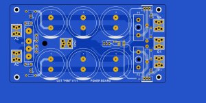
Yes , either "dumb" mode , or (with the simple opto and 2 MOSFET's) - "smart mode". (below - power board).
I fully looked at each section of the protection circuitry. Why are only some of the I/O's I2C addressable ? Is I2C too slow (100khz bus)
for the speaker relays ?
I don't want to reinvent the wheel , just refine it for Arcwelder designs.
I have some really cheap integrated ATmega 324's (chinese nano's) ... bought 5 for 12$ (below 2). Easier to just layout 2 SIP connectors on a custom
control board. Preloaded Arduino bootloader , CH340 UART , regulators + crystal. I use these on my led lighting.
I see the addressable tempco sensor hookup .... just one of those standard hobby arduino sensors (AHT-10 I2C) ?
Really like the MCP23008 , only using one I/O on the VZ PS ... use all those 8 I/0's ! I2C is cool for the temps and display.
On the current sense , exactly what is getting measured - Re ? I want my "mini" OPS to just have the dual opto out (HCPL 2530) and a 5V pin. Better than
having the high level audio output running through a cable.
On both the OPS and PS boards , one can just omit the specified (SMD) components and keep it simple.
OS
Attachments
I preferred to leave the speaker relay direct drive. I don't want to wait for I2C communications to happen in the loop before DC detection is seen. As is it's on an interrupt which jumps to the front of the line in the loop if activated. Same goes for over-current detection. Temperature won't change fast enough to be an issue so it's fine on a databus.
MCP23008 is a great device with one hitch. If you lose connection with it momentarily you can't talk to it again until you reboot the Arduino and re-initialize communications. That's why I went with the PCF8574 in the power supplies. It's a dumb device that doesn't notice if communication is lost.
MCP23008 is a great device with one hitch. If you lose connection with it momentarily you can't talk to it again until you reboot the Arduino and re-initialize communications. That's why I went with the PCF8574 in the power supplies. It's a dumb device that doesn't notice if communication is lost.
Ok , 4 I/0's - edit it has 8 ! , should be enough for supplies. I will be using 2 PS's. With the over-current , how is that hooked to the amp ?That's why I went with the PCF8574 in the power supplies. It's a dumb device that doesn't notice if communication is lost.
OS
We did current sensing with an optoisolator. Use a divider network to tune the voltage that trips it.
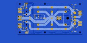
That I knew , like the old "21'st century" setup. So (+/-) on (below) for a single amp would be between emitters of any P/N pair ?We did current sensing with an optoisolator. Use a divider network to tune the voltage that trips it.
Then I could use a single channel opto with (+5V,Gnd.,and control signal) output for each of my OPS's. I'd add the pullup and local decoupling
as needed using optional SMD to my present (through-hole) board.
PS - is the ratio of R17/R18 "tuned" for .22R resistors ?
OS
Attachments

Yes that's tuned for .22R resistors and this optocoupler to activate around 4 amps.
We came up with the idea to add diodes to all of the emitter resistors and sum them together so if there was one transistor current hogging we would catch it. I haven't tested this out in the real world yet though. This would require adjustments to compensate for the extra diode voltage drops.
We came up with the idea to add diodes to all of the emitter resistors and sum them together so if there was one transistor current hogging we would catch it. I haven't tested this out in the real world yet though. This would require adjustments to compensate for the extra diode voltage drops.
- Home
- Amplifiers
- Solid State
- Spooky and Hellraiser SMD 60W amps (Wolverine compatible IPS)