
Lousy footprint for that "821" component, perfect layout my a$$, tell the designer to solder his own up first and figure out his mistakes before making others figure it out for him. Footprints for hand and wave soldering should have larger pad areas and extend well past the terminations so that the hot iron tip does not need to be in contact with the terminations which we all know is what damages them. Also a proper fillet is created.
Last edited:
It is wrong guys..
Hand soldering is impossible 😭
We don't speaking for solder paste not hot air gun.
Hand soldering need larger pads or smaller parts.
Isn't my first smd trying,i have solder many many times.
Hand soldering is impossible 😭
We don't speaking for solder paste not hot air gun.
Hand soldering need larger pads or smaller parts.
Isn't my first smd trying,i have solder many many times.
Attachments

Yes, there is a learning curve for successful SMT soldering no matter what technique you choose. But there are techniques the designer needs to incorporate in the layout to facilitate the DIY'er in successfully assembling an SMT project. I fully agree with the layout tips and tricks that Rsavas points out. The only way to "get it right" is to learn from the mistakes and design the next layout better. IMO, this is a very aggressive project to take on for a first time SMT layout. The circuits might be well vetted but not the layouts of these boards, I hope the bugs get worked out because I would like to build this amp. 😉
Those input boards look familiar! Yes for hand soldering extended pads are necessary. I did a custom library for the boards I layed out. Paste can be used with a conventional iron too though, allowing you to work with pads like this.
Usually it take four spins at a board to get all the kinks out. I did lots where the first round went straight in the trash can due to very obvious mistakes.
Usually it take four spins at a board to get all the kinks out. I did lots where the first round went straight in the trash can due to very obvious mistakes.
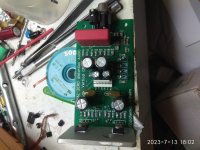
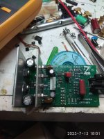
thimios ... sprint layout and BOM said 0805 resistor.Unfortunately,bad knews.
Wrong side pads.
Have a look at this 820R resistor.
It is impossible to solder.
Pads is completely under resistor ,no room for solder tip.

If that was a resistor I sent you it would have been 1206. I hardly ever used 0805. I went straight to 0603 for compact designs.
Kinda helps if you use the right size 🙂 get your calipers out and measure. I thought you are building with parts from BOM which is how one verifies the design and documentation
EIA 1206 is metric 3216
EIA 1206 is metric 3216
^ Also kinda helps if you actually open and review the files provided by the designer before making comments about their design work...
If I could edit my comments I would, now knowing that folks are not checking if they are using the right parts and me assuming that it is the wrong part footprint, so I apologize for making a wrong assumption, carry on
Vunce, please unlike my comments above 🙂
But I still stand behind my statement that OS should be building and testing his designs before releasing them. If something does not go to plan people should not be spending their $ on a hope and prayer.
Edit: I apologize🙂
I have my smt parts in bags labeled by value and size
Last edited:
^ You guess you apologize... okay.
Seriously though... I'm doing that in jest. Not a poke. I've really enjoyed the dialog around these projects.
Either way... on a more positive note... I'm looking forward to seeing how this turns out. I made a quick attempt to learn (I can't point fingers, I'm a total novice)... by taking what was provided in the files and laying them into another piece of software (KiCad) to see if I could get it to do the 3D render. I failed miserably.
I just tried to use some parts from my box.
I don't understand what problem you have.
Pete needs no defense.
He is not in any danger, especially from me.
rsavas,sorry for unintentionally dragging you along.
I don't understand what problem you have.
Pete needs no defense.
He is not in any danger, especially from me.
rsavas,sorry for unintentionally dragging you along.
Pete's amps are always a group effort. Thimios and Terry (Stillforgiven) usually built every design within a day of Pete posting them. This works well. The Slewmasters were awesome amps!
I was trying encourage these designs to be done in kicad, that way everyone can learn to use the tool and have a design to build as a result. You started, all is not lost, just need to learn to drive the tool, it takes time and some frustration doing all on your own as a first design, that’s why they call it painful going through the learning curve on the first go around.Either way... on a more positive note... I'm looking forward to seeing how this turns out. I made a quick attempt to learn (I can't point fingers, I'm a total novice)... by taking what was provided in the files and laying them into another piece of software (KiCad) to see if I could get it to do the 3D render. I failed miserably.
Start with the schematic and then concentrate on layout which is more involved.
Last edited:
Sorry, Thimios...
I don't have a problem at all, with anyone. If my lighthearted comments to rsavas seemed too harsh, apologies. They weren't intended that way.
I hope these projects move forward, and I greatly appreciate your early builds. They pave the way for novices like me.
<moving to the back of the room to observe progress and shutting up now... >
It's probably true that the layout design could've been a lot more DIY friendly, but it is definitely possible to hand soldering/rework. In tight areas and hidden pads where a soldering iron tip can't access the pads directly but the component has plated ends, pre-tin the pads, pile up the flux, use TWO soldering irons and heat the component ends at the same time, and you'll be amazed. Again, use a good flux and pile it up, there is no such thing as using too much flux. Do NOT use lead-free solder. Use 63/37 leaded solder. Set the tip temperature at 325C.It is impossible to solder.
- Home
- Amplifiers
- Solid State
- Spooky and Hellraiser SMD 60W amps (Wolverine compatible IPS)