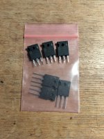
Send me your shipping address and I'll send you the Harris triplet.
Package from Mr. Harris arrived! 😆
After cooking for a couple of hours i now have 212-228mV on all 12 critters. Sub mV offset.
Thank you Pa!

Attachments

Got my BA-3 and Whammy up and running and they sound great! Still chip rolling, but the two are great with my DT-1990 and Clear MG.
As I finished stuffing my F4, the 4U chassis arrived! I gotta say, it's a much tighter fit than I was expecting. I'm thinking about splitting the PSU board so the transformer can be centered. Wiring will be...fun...XD
As I finished stuffing my F4, the 4U chassis arrived! I gotta say, it's a much tighter fit than I was expecting. I'm thinking about splitting the PSU board so the transformer can be centered. Wiring will be...fun...XD
Attachments
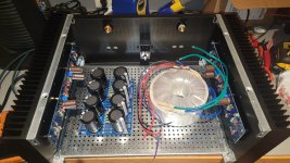
Place the toroid at front and power supply at rear of case near inputs and outputs.
With that chassis, a good way to mount the PSU board is vertically on the inside of the front panel.
Did you try to place the toroid in a upright position? With te cap-bank turned 90° you‘d get a symmetrical arrangement, And you would have all in 1 chassis. Not sure about switch, led, and rectifiers though…
Here’s mine, 4u 300 mini… (toroid laying around under the capbank 🙂 )
Here’s mine, 4u 300 mini… (toroid laying around under the capbank 🙂 )
Attachments
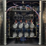
This is a 4U mini-dissipante. I have the utmost confidence your F4 chassis stuffing will be beautiful.

The 4U aluminum with the Antek 400VA will allow the psu to be up on stilts above the transformer as well.
80mm M3 standoffs for drones work well.

80mm M3 standoffs for drones work well.
Wiring coming along! Calling it a night due to lack of usable light and beer. Transformer and power lines to be installed tomorrow or Monday. Yeah, keeping the xfmr on the right side; easier to work and it's an amp, not a jet. I don't care where its CG is!

why I didn't ever think of that - having PSU wires longer to one channel and xformer closer to same one ....... just leads to greater entertainment factor!

...and cheap channel delay for echo effect.why I didn't ever think of that - having PSU wires longer to one channel and xformer closer to same one ....... just leads to greater entertainment factor!
So that isn't going to work then. Great. I think I've been at this too long. Gonna put this away for awhile and go do something else.
You should see what I've done to stuff two F6 dual mono power supplies into one 5U!
Dare to be different!!!
Dare to be different!!!
you have myriad of pics, taken from Kosher builds
if you keep it symmetrical, no troubles
xformer all the way up to front plate , then bridges then Cap Bank centrally
equal length of power wires to channels, easy arrangement of signal wires to avoid ground loops
as I'm always saying - if in doubt - look at original FW pics - plenty of those around
6moons site, for example - almost every FW amp covered with high res content
naah, I'm not that clever
but, with time, I'm trying to learn who is .......

but, with time, I'm trying to learn who is .......
To Luddites it is you...but, with time, I'm trying to learn who is .......

F4 up and running. Right board biasing at 135mV/0mV, left board 270mV/0mV. Left P1 is maxed out with 4.75k resistor at R9.
Why are both sides biased at such significantly different levels? I believe the target is 0.2V across the 0.47R source resistors.
Are you saying you can't get the bias on the left board lower than 0.27V across the 0.47R resistors?
Are you saying you can't get the bias on the left board lower than 0.27V across the 0.47R resistors?
- Home
- Amplifiers
- Pass Labs
- A guide to building the Pass F4 amplifier