Any opinion on whether it’s overkill to have each driver in its own volume?
I’m planning to start by dividing each side into 6 groups (2s2p). So I could use fewer dividers to make 6 volumes instead. That would allow for more chamfers.
Would you do your groupings the same still? I think you said your build was 5 groups?
I’m planning to start by dividing each side into 6 groups (2s2p). So I could use fewer dividers to make 6 volumes instead. That would allow for more chamfers.
Would you do your groupings the same still? I think you said your build was 5 groups?
I wouldn't say it is overkill to have them separate but I doubt you will see much benefit either way.Any opinion on whether it’s overkill to have each driver in its own volume?
I’m planning to start by dividing each side into 6 groups (2s2p). So I could use fewer dividers to make 6 volumes instead. That would allow for more chamfers.
I wouldn't split them into smaller sections as that does tend to exacerbate differences between the drivers. When I did that I saw a more uneven impedance peak. Sorting the drivers into groups that had the most similar impedance peak frequencies, did make for a nicer impedance graph but I could not tell the difference between them while listening. If I did it again I would make it one overall chamber with matrix style bracing.
Would you do your groupings the same still?
As I have started experimenting with frequency dependent shading, the grouping I would choose would probably cater to that functionality if I were to redo it from scratch. I do have 5x5.
I did not really give each driver it's own compartment, but based on something Lynn Olsen said in his big beyond the Ariel thread I did close up the first part between drivers. The plan from the start was to use each divider as a brace. I don't think it's really needed though, but it's easy to overthink things when you're building and still reading the forums (lol).
That black part was the result, a piece of mass loaded vinyl between each driver where the connectors face each other. There are holes in each brace to make it one space.
Found the quote that made me doubt using an open shared space between drivers:
Speaker cones are close to acoustically transparent, with only a few dB of loss. (How much acoustic isolation would you expect from a wall made of paper?)
If the two (or more) drivers share a common rear chamber, the out-of-phase radiation from one driver will go through the cone of the other driver, with a bit of additional time delay thanks to the transit time between the two drivers. The net result is degraded time response and (fairly small) ripples in the frequency response. Subjectively, the midrange is muddled and confused-sounding, as you would expect with time-delayed artifacts in the 1 mSec region.
The solution is to have an isolated chamber for each driver ... although the bass vents can be shared, since the contemplated vent system has both vent damping and a folded path from the inside of the enclosure to the outside.
This was a lesson-learned from the Ariel ... an early version with a shared chamber sounded quite bad, while measuring pretty well. The rear-wave crosstalk isn't obvious on FR measurements unless you're looking for it, while the time-domain degradation was somewhat more obvious and clear with respect to the phase of the delayed rear-wave. (One of the things to always remember with FR measurements is the phase and time information has been discarded ... and phase and time information can be useful for diagnostic purposes.)
Although it's easy to abuse time-domain information for marketing purposes, it is an excellent diagnostic for tracking down colorations that aren't apparent on FR graphs. When loudspeakers use a common shared rear chamber (frequently seen in commercial line-source speakers), the delayed and inverted "echo" of the first-arrival sound is revealed in the time-domain graph ... provided the driver is clean enough to reproduce a recognizable impulse, and the response is not cluttered with box-edge diffraction.

Thanks for digging that up. So I’ll aim to divide them all, and with some rock wool we can keep the rear wave away from the cone.
the wiring I’ll keep 2s2p for now. That’s 6 groups per tower. I’m running each wire down to the bottom, so I can reconfigure later if it needs it.
Its so stupid hot and humid that I decided not to paint-sand today.
I ended up dragging the parts for one tower to the basement for a test-fit. Good news- everything fits reasonably well.
The bad news is the rebates on the side walls are flipped. The front should have a 0.125” rebate, the rear 0.25”. So the fit is good—but the cutouts for the transmission line are facing the wrong way. I could just skip that and leave the interior as a plain rectangle, or do some trimming of the non-rebate area. Rookie mistake to not make the part symmetrical.
I’m gotta dig up the final plans and see who made the oops. The shop had to redraw my plans because of a file compatibility issue, could have happened there.
It’s clear now I’m going to need a lot more clamps.
After some clamping I put it close to the final placement without its base. it fits the height perfectly. It’s a lot! I may end up doing some grille cloth or strings across the front to make it feel less…intimidating. Thankfully there’s no decor concerns in this half of the basement.
Don’t judge the absolutely terrible state of the “lab”!
Be sure that I did not tell you that story to convince you to divide the drivers like I did.
I read that post from Lynn when I still had a chance to act on it by sealing off the first part for each driver. But I can't honestly tell you if it is better/worse or just different. I acted because I wasn't sure myself. I remember posting about it and saying I shouldn't read any more posts like that before finishing the arrays, because I'd keep changing the concept each time I'd read some contradictory information 😉.
So even now I'm still not sure if it will change anything if the space between drivers is kept open. I had to make a call and I did. Just like you are doing now? 🙂
Good idea to keep the wires accessible, though it might lead to very long runs of wires. I don't remember who but I do recall someone that made a pair of connectors for each driver on the back of the enclosure. Making it possible to rewire everything as he saw fit from the outside. Pretty clever.
Well, a little less than a year and I have this to show for it:


Second one is about halfway finished.
I'm working out the shading and delays to try and make it sound good before putting it in a safe place for a few months while its pair is finished.
I have a roughly calculated CBT shading/delay in the dsp right now. It is very cool how it doesn't change all that much around the room, it does cause some oddities where your brain tries to figure out where the source actually is along the line.
I definitely sit too close to the floor at main listening position for the ground-plane cbt topology to work best. The biggest benefit is kinda lost there vs standing. The clarity is phenomenal but it doesn't sound "big".
Going to try a few other topologies and see what I can do to improve things at main. I do miss my open baffle setup right now- this thing is huge- and its at this rough place and needs refining. Something with the bass/midbass that feels thin/lacking.
Still, theres a ton more work ahead to finishing the base for this tower, the second tower, and build out the wire harnesses to be nice and neat.
I'd say try VituixCAD to simulate your shading and see what it does 👍.
Better than flying blind if you ask me... On @nc535's thread there's a starter model you can use to hit the ground running.
Link: https://www.diyaudio.com/community/...-corner-placement.337956/page-28#post-6205129
Better than flying blind if you ask me... On @nc535's thread there's a starter model you can use to hit the ground running.
Link: https://www.diyaudio.com/community/...-corner-placement.337956/page-28#post-6205129
Would the most effective thing be to measure it a specific way inside or outside? Then model the responses further in vituixcad?
The plan is to pack up this single tower and its dsp+amp after this week, until the second tower is complete, and I can set up a more permanent install.
I want to make a good set of measurements to use with modeling, that way I can make some kind of progress on these when I cant get be assembling.
Any thoughts on what and how to measure? I have a large yard area that can manage about 25' to the nearest solid object.
I would measure one driver in the cabinet (with the others shorted if that is practical) at a defined distance, something close to your listening distance if that is feasible. Then use that in the Vituix modelling scheme linked to before. Trying to measure a line array all in one go and use that measurement to decide on processing is an exercise in futility.
If you weren't shading I would say go straight to in room measurements and work from there based on what you hear.
If you weren't shading I would say go straight to in room measurements and work from there based on what you hear.
Totally agree with @fluid, measure one driver with all off axis angles you need. Use that data in Vituixcad as driver data and build up the array.
If you can, save a measurement of the array firing all drivers unshaded and compare notes with Vituixcad's simulation doing the same.
That should give you some confidence in Vituix's abilities.
Next you can work out the shading needed to get an even coverage and see what you're getting.
I have only worked with simulated driver data but I could compare it to my years worth of measurements to see if it made any sense. The accuracy surprised me and gave me confidence to work on a schematic for a frequency shading concept.
Its wired with each adjacent driver pair in parallel, each driver has its own sealed volume, 12 pairs for the line...
So measurements of just a central pair would be sufficient to model with?
So measurements of just a central pair would be sufficient to model with?
I have plans to move the array outside next week to do a good set of measurements for the center drivers. In the meantime I'll try to get some 1m measurements inside and work with those.
I have been playing with the sim from @nc535 and restructured it to fit how I have my array wired and set up with DSP.
I configured it with progressive low-pass and delays ranging out from the center. What should my goal be for aligning the phase responses? I tried to use the delay to get them to align, and weighting the low-pass to shape the overal tilt of the response. Is this approach sensible? Or should I be trying another method?
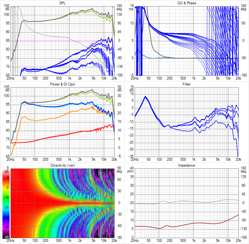
Adjusting the delay like that would get you a focused array. Which could make for a very narrow vertical sweet spot that should show up in the vertical directivity plot. The horizontal plot will pretty much look the same for all shading types, so I suggest to either switch the horizontal plot or Impedance plot to show the vertical directivity instead.
The CBT would be the opposite of what you are doing in an attempt to get a more even directivity over a larger area. It will show some comb effects because of the driver to driver spacing.
The results you have here are not what I would expect, but I'd still like to see the vertical plot. In this post: https://www.diyaudio.com/community/...range-line-array.242171/page-400#post-7492870 I have simulations of a focused array, CBT array, my own frequency shaded array and an unshaded array. It may come in useful for comparisons. What you see in my focused array simulation is that it sums up pretty good:
Yes. I would add a line of 16 Dayton ND20FB tweeters to each array mounted along the line to provide a focused listening window of roughly 36” in the vertical. For $325 or so, all of your problems are solved with an improved combined power response where you need it most.. Is this approach sensible? Or should I be trying another method?
While I hail the accomplishments of those designing and building these types of arrays, I find them to be more of exercise in what could be done, rather than what should be done. A lot of this depends on your beliefs. If you’re in the camp that the performance factor of a speaker can be fully resolved by measurements alone and there’s no remaining subjective components or otherwise ’unmeasurable’ quality to a system, proceed as you are. After decades of designing systems for custom studio installations and the occasional home use speaker, I can only share my personal experience……measurements are certainly useful, but far from an accurate sum of actual performance.
When I was thinking of building one of these, I did as some here have suggested…..built each driver into its own enclosure within an extended baffle to simulate the reflections and diffraction and measured. I tried 6 drivers. After measuring extensively, since these were full range, I just listened to each for a few hours in the near field…….around a meter away In a triangle and slightly off axis. I must tell you that NONE of the extended listening tests of the individual drivers resulted in anything I ever thought I could live with when focusing on the 3-6khz range for uncontested detail. NONE of these drivers provided the clarity IMO that a dedicated tweeter could offer with its smaller surface area and lighter, faster diaphragm. Adding in an on hand Fountek ribbon tweeter using the outputs of my pro interface and DSP at 3.5khz was a very revealing exercise as the improvement was so stark as to finally end the quest once and for all before building one of these for myself.
Mind you, I have built a few for friends, most notably one for a 5 piece all acoustic and vocal group who cover popular songs and it works very well for them as the arrays can be placed behind them and provide monitoring as well without feedback.….a cheaper alternative to the less capable stick PA commercial offerings for sure. This build used the Faital Pro 3FE driver 16ohm version with 16 in total per side powered with 4 channels of ICE amps built in. In this application, these were never going to supply the low end needed for a large space so that was never a design parameter……only higher output so 16 were all that was needed when high passed at 200hz to a single 12” subwoofer per side.
- Home
- Loudspeakers
- Full Range
- TC9 active line array questions