For a random point of the triangle wave (V3) your circuit keeps Ic constant for transistors with different betas. So the output of INA is constant. Also ramp voltage is constant.
To achieve this, for low beta transistors U3D raises its output voltage, because more base current and thus higher input voltage for the current source is needed.
So that voltage is some kind of inverse function of beta. It means, it is not possible to retrieve beta from U3D output voltage.

To achieve this, for low beta transistors U3D raises its output voltage, because more base current and thus higher input voltage for the current source is needed.
So that voltage is some kind of inverse function of beta. It means, it is not possible to retrieve beta from U3D output voltage.
The upper part of your circuit resembles mine, but the lower half is puzzling me. You're measuring Ib and put that in a multiplier with the output triangle from the IC INA, its output folding back to the current node of your X7. I've no idea what's going on there. The led displays a beta... a static value?
But not for 'low beta bjt's' only, but for any value of beta during the transition of the applied waveform (triangle/sawtooth).
The output of U3D looks like the indicated 'adjusted sawtooth' waveform (the double medieval soldier helmets: "wilhelms").
At low currents, the beta is low so the wilhelm raises sharp until the mid-beta area, where the waveform flattens out, to raise again at higher currents (wilhelms peak). The triangle descends and the mirroring waveform appears. As two triangles are shown as an example, two peaked helmets appear.
The output of U3D is the original triangle PLUS the 'beta-compensation.
Subtract the original triangle from it to yield that beta-compensation (U3A).
Invert (U3C), output is the Y-signal.
It is not needed to measure the Ib also, as this already incorporated in the compensation signal.
Output of the INA (U1) is the X-signal, X and Y are always synchronous.
X and Y to connect to an X-Y configured oscilloscope (not a dc or ac meter).
TINA TI simulator has this available, but I'm currently exploring its capabilities.
I don't know if your simulator has this option.
Mark's point (#39) is the have a (>) 4 decades logarithmic (10^x) sweep, so the triangel should be 'deformed' to a exponential 4-dec' (10^x) sweep, which makes it rather difficult for this betatracer circuit, as I expect for now.
Not Ic constant as a static DC value, but forcing to correspond with the original (AC) triangle from U2D (your X4).For a random point of the triangle wave (V3) your circuit keeps Ic constant for transistors with different betas. So the output of INA is constant. Also ramp voltage is constant.
Exactly, U3D compensataes until the output of the INA U1 (your X2) matches the output of U2D (the triangle).To achieve this, for low beta transistors U3D raises its output voltage, because more base current and thus higher input voltage for the current source is needed.
But not for 'low beta bjt's' only, but for any value of beta during the transition of the applied waveform (triangle/sawtooth).
The output of U3D looks like the indicated 'adjusted sawtooth' waveform (the double medieval soldier helmets: "wilhelms").
At low currents, the beta is low so the wilhelm raises sharp until the mid-beta area, where the waveform flattens out, to raise again at higher currents (wilhelms peak). The triangle descends and the mirroring waveform appears. As two triangles are shown as an example, two peaked helmets appear.
Yes!So that voltage is some kind of inverse function of beta.
No!It means, it is not possible to retrieve beta from U3D output voltage.
The output of U3D is the original triangle PLUS the 'beta-compensation.
Subtract the original triangle from it to yield that beta-compensation (U3A).
Invert (U3C), output is the Y-signal.
It is not needed to measure the Ib also, as this already incorporated in the compensation signal.
Output of the INA (U1) is the X-signal, X and Y are always synchronous.
X and Y to connect to an X-Y configured oscilloscope (not a dc or ac meter).
TINA TI simulator has this available, but I'm currently exploring its capabilities.
I don't know if your simulator has this option.
Mark's point (#39) is the have a (>) 4 decades logarithmic (10^x) sweep, so the triangel should be 'deformed' to a exponential 4-dec' (10^x) sweep, which makes it rather difficult for this betatracer circuit, as I expect for now.
Attachments

Ok, some misunderstandings.
I wrote: For a random point of the triangle wave (V3) your circuit keeps Ic constant for transistors with different betas.
V3 is a sample of the triangle. I do that for simplicity of dc analysis. Low beta was only an example of different betas..
Your circuit linearizes and adjusts the measured Ic, in the schematic it is 10mA for all betas.
Maybe not on the low and high end of the beta range... For beta lower than 100, the opamp may hit the V+ rail.
(And looking at the whole triangle, the IC span is the same for different betas.)
.
.
.
So, regardless how the compensation curve for the whole triangle looks like...
At the sampling point, where Ic is 10mA, we have the following output voltages on the regulating opamp:
Low beta BD139: hfe = 105, Vout = 11,52V Vbeta-compensation = 6,52V
Medium beta BC239: hfe = 271, Vout = 7V Vbeta-compensation = 2,00V
High beta BC550: hfe = 448, Vout = 5,88V Vbeta-compensation = 0,88V
hfe = up --> Vout & Vbeta-compensation = down and vice versa.
That definitely means, for low beta, your Y voltage is high and for high beta, it is low.
Vbeta-compensation is not beta but something like 1/beta.
Inverting Vbeta-compensation mirrors the curve visually only.
But... the beta compensation is the error compensation voltage that is generated such that the specific current source drives the base to accomplish linearity.
How do you come from the beta-compensation voltage to the actual beta value?
What is the mathematical relationship ?
How does the formula look like ?
Also Vbeta-compensation depends on the voltage divider.
Not Ic constant as a static DC value, but forcing to correspond with the original (AC) triangle from U2D (your X4).
But not for 'low beta bjt's' only, but for any value of beta during the transition of the applied waveform (triangle/sawtooth).
I wrote: For a random point of the triangle wave (V3) your circuit keeps Ic constant for transistors with different betas.
V3 is a sample of the triangle. I do that for simplicity of dc analysis. Low beta was only an example of different betas..
Your circuit linearizes and adjusts the measured Ic, in the schematic it is 10mA for all betas.
Maybe not on the low and high end of the beta range... For beta lower than 100, the opamp may hit the V+ rail.
(And looking at the whole triangle, the IC span is the same for different betas.)
.
.
.
So, regardless how the compensation curve for the whole triangle looks like...
At the sampling point, where Ic is 10mA, we have the following output voltages on the regulating opamp:
Low beta BD139: hfe = 105, Vout = 11,52V Vbeta-compensation = 6,52V
Medium beta BC239: hfe = 271, Vout = 7V Vbeta-compensation = 2,00V
High beta BC550: hfe = 448, Vout = 5,88V Vbeta-compensation = 0,88V
hfe = up --> Vout & Vbeta-compensation = down and vice versa.
That definitely means, for low beta, your Y voltage is high and for high beta, it is low.
Vbeta-compensation is not beta but something like 1/beta.
Inverting Vbeta-compensation mirrors the curve visually only.
I agree with that.The output of U3D is the original triangle PLUS the 'beta-compensation.
Subtract the original triangle from it to yield that beta-compensation (U3A).
But... the beta compensation is the error compensation voltage that is generated such that the specific current source drives the base to accomplish linearity.
How do you come from the beta-compensation voltage to the actual beta value?
What is the mathematical relationship ?
How does the formula look like ?
Also Vbeta-compensation depends on the voltage divider.
Last edited:
Yes, sense Ic and sense Ib, do the division to get beta by definition. V(Ic)/V(Ib) = Vbeta. Circuit is adjusted so that 1V Vbeta = beta 100.The upper part of your circuit resembles mine, but the lower half is puzzling me. You're measuring Ib and put that in a multiplier with the output triangle from the IC INA, its output folding back to the current node of your X7. I've no idea what's going on there. The led displays a beta... a static value?
AD633 is a multiplier in the feedback loop of the opamp, that forms a divider. I borrowed that from the datasheet.
AD633 pin3 is -4,48V, inverted gives readout 4,48 = beta 448. Ignore the decimal point.
The LED is a voltmeter that directly displays beta at the sampling point of the curve where Ic is 10mA.
A 3 1/2 digit voltmeter could display beta up to 1999. Then 100mV = beta 100.
In the real world, with a sample/hold, it can display beta for any Ic point on the curve in conjunction with a cursor, as I mentioned before.
Last edited:
Bernhard, we look different to this circuit, and that's ok!
The voltages listed are '5V' plus compensation. What's this '5V'?
The output of the INA must follow the source waveform (trangle).
Second line: no, it cannot be 1/beta. An inverting function is different from reciprokal function.
It is inverted, not reciproked.
As the compenstion is added (not multiplied!!! -> 'AM'!) to the triangle (by U3D), subtraction of that same (original) triangle reveals the needed compensation.
The compensation is high where the beta is low, and vv. That requests an inverter (not a 1/x function) only to have the beta shown, related to the up and down moving triangle.
(*) different from a regular AM with a modulated carrier - I mean to express the amplitude change of the modified triangle (aka 'carrier')
The mathematical relationship will be a first-degree comparison formula... yet to figure out. I'll try to find that one, but's elaborate.
As Tina has this XY capability, I'm drawing a basic version now... needs some time too.
What is 'constant'here? The DC or momentary AC value? Is Ic made 'constant' (a certain value) for any bjt despite it's beta?For a random point of the triangle wave (V3) your circuit keeps Ic constant for transistors with different betas.
So all bjt's, no matter what their spec's, the Ic will become 10mA whatsoever? (That would be the INA.)Your circuit linearizes and adjusts the measured Ic, in the schematic it is 10mA for all betas.
Yes, both true, so scaling and further adaptation is needed. It's in development state!Maybe not on the low and high end of the beta range... For beta lower than 100, the opamp may hit the V+ rail.
Is this 'sampling point' the same as the 'random point'?At the sampling point, where Ic is 10mA
The voltages listed are '5V' plus compensation. What's this '5V'?
True when measured the static (momentarely?) value. But the triangle runs up and down continuously, and so the the compensation value too.hfe = up --> Vout & Vbeta-compensation = down and vice versa.
The output of the INA must follow the source waveform (trangle).
First line: yes.That definitely means, for low beta, your Y voltage is high and for high beta, it is low.
Vbeta-compensation is not beta but something like 1/beta.
Inverting Vbeta-compensation mirrors the curve visually only.
Second line: no, it cannot be 1/beta. An inverting function is different from reciprokal function.
It is inverted, not reciproked.
The last word: "linearity" ??? Linear the follow the source waveform: yes. Linear to flatten beta out: no. (not that I can imagine...)But... the beta compensation is the error compensation voltage that is generated such that the specific current source drives the base to accomplish linearity.
The compensation is 'amplitude-modulated' upon the source waveform (triangle) (*). Where there is lack of sufficient beta, more is compensated (low and high values of Ic). It is forced so by the feedback loop. (U3D is the 'triangle value comperator').How do you come from the beta-compensation voltage to the actual beta value?
What is the mathematical relationship ?
How does the formula look like ?
As the compenstion is added (not multiplied!!! -> 'AM'!) to the triangle (by U3D), subtraction of that same (original) triangle reveals the needed compensation.
The compensation is high where the beta is low, and vv. That requests an inverter (not a 1/x function) only to have the beta shown, related to the up and down moving triangle.
(*) different from a regular AM with a modulated carrier - I mean to express the amplitude change of the modified triangle (aka 'carrier')
The mathematical relationship will be a first-degree comparison formula... yet to figure out. I'll try to find that one, but's elaborate.
All scalings are to be defined, just put in some generic values around the opamps and the INA as a starter.Also Vbeta-compensation depends on the voltage divider.
As Tina has this XY capability, I'm drawing a basic version now... needs some time too.
Ah, so that's a static value indeed.In the real world, with a sample/hold, it can display beta for any Ic point on the curve in conjunction with a cursor, as I mentioned before.

The dc value which is a sample of the momentary ac value.What is 'constant'here? The DC or momentary AC value? Is Ic made 'constant' (a certain value) for any bjt despite it's beta?
Sampled Ic is constant at 10mA for all mentioned transistors, regardless of beta. Because the circuit is in the feedback loop of the opamp.
Yes, as I said.So all bjt's, no matter what their spec's, the Ic will become 10mA whatsoever? (That would be the INA.)
5,02V is the randomly chosen sampling point on the triangle.Is this 'sampling point' the same as the 'random point'?
The voltages listed are '5V' plus compensation. What's this '5V'?
Does not matter if the beta is low or high because of transistor type, temperature or Ic. Output of U3D will be higher with lower beta and vice versa.True when measured the static (momentarely?) value. But the triangle runs up and down continuously, and so the the compensation value too.
The output of the INA must follow the source waveform (trangle).
I do not know what it is exactly but if you put a diode ( e function ) in the feedback loop you get a log amp.Second line: no, it cannot be 1/beta. An inverting function is different from reciprokal function.
It is inverted, not reciproked.
If you put a multiplier in the feedback loop you get a divider.
What do you get if you put the beta function in the feedback loop ?
Yes, it flattens out the beta function, reason why Ic is constant for all transistors*, and so the -input follows the +input which is the triangle.Linear to flatten beta out: no.
*The output of the INA is on -input of U3D and that is the sensed Ic and that is held constant.
subtraction of that same (original) triangle reveals the needed compensation.
The compensation of beta is not beta.The mathematical relationship will be a first-degree comparison formula...
Please show me the formula.
In two parts, first the easiest one Vx:
Vu3d = Ao*(Vg - Vx)
Vr40 = k4*Ao*(Vg - Vx)
Ib = Vr40/R5 (Acs=1)
Ib = k4*Ao*(Vg-Vx)/R5
Ic = ßk4*Ao(Vg-Vx)/R5
INA:
Vx = Aina*(Vps - Rm*I)
Vx = Aina*(Vps = Rm*ßk4*Ao(Vg-Vx)/R5)
Vx = Aina*Vps - (Rm/R5 * ß*k4*Ao*Aina)*Vg + (Rm/R5 * ß*k4*Ao*Aina)*Vx
assume H = Rm/R5 * ß*k4*Ao
Vx = Ai*Vps - H*Aina*Vg + H*Aina*Vx
Vx = { Aina*Vps - H*Aina**Vg } / { 1 - H*Aina }
H*Aina >> 1 (~ 100...)
Vx = Ai/(-HAina) * Vps - H*Aina/(-H*Aina) * Vg
Vx = Vps/-H + Vg [ H = Rm/R5 * ß * k4 * Ao = 1/100 * ß * 1/100 * 10^5 = 10 * ß = [100 <> 1000] )
thus: Vx = ... Vg
I need some more time for the beta equation.
it's the compensation of beta plus the source waveform.The compensation of beta is not beta.


One of my grandious errors!INA:
Vx = Aina*(Vps - Rm*I)
Actually, it is Vx = Aina * ( Vps - (Vps - Rm*Ic) ), thus the more simple Vx = Aina * Rm * Ic.
Anyhow, the result is the same: (1 + Ao) * Vx= (Ao) * Vg (Ao is the open loop gain of U3D).
So, Vx = Vg (The output of the INA is the same as the source waveform.)
For the Y-channel:
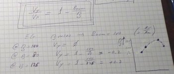
Vz = (Bnom / ß) * Vg (Vz is the output of U3D, 'Bnom' is the nominal beta (say "100"), ß is the actual beta)
Restrictions and revelations:
R55/Rmeas equals Bnom, Aina equals ( 1 / k4 ) (k4 = R40 / (R40 + R44) ) and equals Bnom also.
This brings the relation between Ib and Ic to an optimum.
The Y-output related to the X-output:
Vy / Vx = ( 1 - Bnom / ß )
If ß differs from Bnom, the curved beta is traced on the scope.
Attachments
As the compenstion is added (not multiplied!!! -> 'AM'!) to the triangle (by U3D), subtraction of that same (original) triangle reveals the needed compensation.
Vo = opamp VoutVz = (Bnom / ß) * Vg
Vi = opamp Vin- = opamp Vin+
Bn = beta nominal
sensed Beta = Bs
Vo = Bn * Vi / Bs
Bs = Bn * Vi / Vo
Bn = constant = C -> Bs = C * Vi / Vo
Vi = Ic * R * gain & Vo = Ib * R * gain
Bs = C * Ic * R * gain / Ib * R * gain
Bs = C * Ic / Ib = beta = hfe
Not exactly sure about C, maybe the gain of the voltage divider and V/I converter...
... however: beta = Ic / Ib

- Home
- Design & Build
- Equipment & Tools
- Transistor HFE - IC curve tracer?