The VBE multiplier isn't going to have enough dynamic current capability to overcome the FET gate capacitances at higher frequencies. The drive voltages you require along with more current won't be there if you only just raise the value of R655.
so this is what i have currently
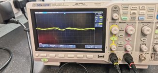
ist picture is the left channel, a little bit of noise but you can play music without hearing it, the second one, left channel is obviously an AC issue
I am currently working my way around with the scope see if i can spot where the issue is.
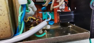
3rd pic is the mains switch has obviously been changed, but i cant see why this would meake any difference
ist picture is the left channel, a little bit of noise but you can play music without hearing it, the second one, left channel is obviously an AC issue
I am currently working my way around with the scope see if i can spot where the issue is.
3rd pic is the mains switch has obviously been changed, but i cant see why this would meake any difference
Attachments

I mentioned this in another thread just a few minutes ago ! The value of gate stopper resistors can be changed to compensate for the different input capacitances of the P and N- channel MOSFETs. You can bring the slew rates of the two halves to be close to equal with a slight benefit to lower THD% (It was in a TI/Nat Semi application note https://www.ti.com/lit/an/snaa045a/snaa045a.pdf). The author of the apnote also came up with some optimal bias levels for different MOSFETs.

I dont have any issue driving the FETS at all, the good channel sounds great, even at high volume levels, I just have an issue with some back ground noise on the other, thats all 👍
I mentioned this in another thread just a few minutes ago !
The NAD is subjectively really good sounding but technically it can't come close to the distortion figures the LM4702 can achieve. I've never seen presets used for gate resistors before, that really is tweaking down to a quarter of a half of nothing.
An interesting read though, thanks 🙂
ist picture is the left channel, a little bit of noise but you can play music without hearing it, the second one, left channel is obviously an AC issue
I am currently working my way around with the scope see if i can spot where the issue is.
3rd pic is the mains switch has obviously been changed, but i cant see why this would meake any difference
Is the switch the correct one? Remember the NAD has that weird 3rd contact used to operate the muting at switch on and switch off.
Isolate the power amp from the preamp which I think can be done with the socket configuration on the rear panel and fit shorting plugs to the power amp input sockets. That should be quiet.
If the frequency of the noise in that 2nd picture is 50Hz then it is possibly being picked up as stray 'radiation' from the transformer and that is inducing a current (voltage) into the wiring somewhere. Hum and noise from the rails usually has a spiky buzzy quality and would be at 100Hz (for UK mains).
It shows 10MHz on scope, is it right? If so, increase gate stoppers.
Also Q619/621 can be omitted with MOSFET outputs.
Also Q619/621 can be omitted with MOSFET outputs.
These are already removed 👍It shows 10MHz on scope, is it right? If so, increase gate stoppers.
Also Q619/621 can be omitted with MOSFET outputs.
so something i have never come across yet
The noise is increased by increasing the bias.If you lower the bias to 0 the noise is almost, but not totaly gone, and the lower it goes the frequency and tone changes
The noise is increased by increasing the bias.If you lower the bias to 0 the noise is almost, but not totaly gone, and the lower it goes the frequency and tone changes
When you increase the bias you increase to loading on the supply and that in turn increases the ripple voltage on the rails. So it would seem at face value the noise is being introduced either via a rail or via a signal ground that has ripple current flowing through it.
Have you ever made this modification on a dual mono amp?
Wouldn't you have a ground or galvanic coupling problem?
highlighted by the assembly of the mos.
Wouldn't you have a ground or galvanic coupling problem?
highlighted by the assembly of the mos.
Wouldn't it be affecting both channels though if it was on the railsWhen you increase the bias you increase to loading on the supply and that in turn increases the ripple voltage on the rails. So it would seem at face value the noise is being introduced either via a rail or via a signal ground that has ripple current flowing through it.
That depends...
Perhaps there is a problem with some rail decoupling on one channel or (and I think morel likely) there is a ripple current flowing through a signal ground. These kind of problems are not always easy to find though. You have to look at the circuit and the PCB and wiring layout and see where noise can enter.
Its also a big clue knowing what the frequency is, 50Hz or 100Hz in the case of hums and buzzes.
Never done one on a dual mono 👍Have you ever made this modification on a dual mono amp?
Wouldn't you have a ground or galvanic coupling problem?
highlighted by the assembly of the mos.
I'm going with grounding at the moment using the scopeThat depends...
Perhaps there is a problem with some rail decoupling on one channel or (and I think morel likely) there is a ripple current flowing through a signal ground. These kind of problems are not always easy to find though. You have to look at the circuit and the PCB and wiring layout and see where noise can enter.
Its also a big clue knowing what the frequency is, 50Hz or 100Hz in the case of hums and buzzes.
I would fault find with the inputs to the power amp shorted on the rear panel. Identify the noise you hear on the scope and determine the frequency. If it sinusoidal like you showed in that scope shot and if it is 50Hz then it could be induced hum from the transformer.
Identify what you are looking at and looking for first.
Identify what you are looking at and looking for first.
- Home
- Amplifiers
- Solid State
- NAD 3140 Conversion to lateral FETS