The emitter current is an exponential function of Vbe. There is also a null around which distortion drops like a rock. See the graphs on my website.
Class A would achieve lower distortion with a much simpler circuit.
Ed
Class A would achieve lower distortion with a much simpler circuit.
Ed
Loading the output with 12pF changes nothing; forcing the OP into class A (it is the only section operating in class AB) provides a marginal improvement, at the cost of a greatly increased dissipation

The open-loop distortion is 1.7%, which may look large but is in fact normal for an amplifier having no degeneration at all. Your "purpose-designed" class A would have degeneration, because the raw gain is much too large to be usable: in this case, it is 95dB @ 1MHz (130dB at lower frequencies).
In open-loop, the distortion is almost pure H2, certainly caused by the imperfect complementarity of the devices.
With the loop closed, the THD should fall to ~1.5ppm, but it is not the case, and the closed-loop THD is mainly H3 and H5, thus quite different. There is a hidden distortion mechanism somewhere.
Forcing the output stage in class A changes practically nothing, both for open and closed loop
That is true only when the sole trade-off is between global and local feedback. Starting from a more linear amplifier improves all cases.Forcing the output stage in class A changes practically nothing, both for open and closed loop
Ed
Can you give a suitable example of such an amplifier?Starting from a more linear amplifier improves all cases.
Ed
Your requirements are different enough from audio that I don't see an example.
Class A has the advantage that the max/min ratio of currents can be chosen to produce arbitrarily low distortion. Feedback can then be applied, which will be mostly local for operation up to 1MHz.
The closest examples I can think of are video amplifiers.
Ed
Class A has the advantage that the max/min ratio of currents can be chosen to produce arbitrarily low distortion. Feedback can then be applied, which will be mostly local for operation up to 1MHz.
The closest examples I can think of are video amplifiers.
Ed
I am still trying to improve my amplifiers, and the best candidate so far is the Groner-based one, but I am faced with a strange behaviour: when the compensation cap C1 is too small (12p), the THD is relatively good (0.003%), and logically the FR has a nasty peak due to insufficient margins.
If the cap is increased to 22p, the FR is ~flat, and the THD increases, which is to be expected. What is surprising is the magnitude: it shoots to 0.015%, a five-fold increase, when the cap value is not even doubled.
In addition, the circuit tolerates an output-inclusive scheme, which means that increasing the compensation should have a minimal effect on the THD.
Can someone explain that paradox?
View attachment 1188649
Input stage distortion from Q9 and Q10 maybe? They supposedly cancel out each other's even-order distortion, so doubling the signal current through them should increase their contribution to the distortion by at least a factor of eight.
Correct: this is the collector current for 12p and 22p:

I do not see how to implement a compensation scheme that doesn't end with the same result.
Instead, maybe an increase of the standing current to minimize the relative variation?
I do not see how to implement a compensation scheme that doesn't end with the same result.
Instead, maybe an increase of the standing current to minimize the relative variation?
Thanks, but the large signal THD is 6 times that of the circuit in #51:

I have tried the darlington output on that one, but it doesn't give a significant improvement
I have tried the darlington output on that one, but it doesn't give a significant improvement
That amp ?? Been around the block with this topology,
-Groner style
-CFA
As far as distortion and stability - this was built 8 years ago , very reliable (for audio).
What do you mean "work up to 1mhz" OLG unity ??
Never tried that ??
Looks very similar to my "hellraiser" (below)I am currently trying to design an amplifier for the output of a generator. It needs to work at up to 1MHz, and have a negligible distortion, ideally in the ppm range whilst delivering 30 to 40Vpp.
This is my first tentative:
-Groner style
-CFA
As far as distortion and stability - this was built 8 years ago , very reliable (for audio).
What do you mean "work up to 1mhz" OLG unity ??
Never tried that ??
Give this a try, simulation is not too bad and in real life measurements is pretty okay as well. Was flat to 10 MHz. THD is very low as well. Perfect for signalgenerator ourput

Last edited:
Not really: this is a high power RF amplifier, but I need an instrument amplifier, capable off DC to 1MHz having a near-perfect linearitySuitable?
It has to remain perfectly linear from DC to 1MHz, whilst pushing 15V into 50 ohmWhat do you mean "work up to 1mhz" OLG unity ?
One of my previous iterations looks very much like it, except for the input LTP's.Give this a try, simulation is not too bad and in real life measurements is pretty okay as well. Was flat to 10 MHz. THD is very low as well. Perfect for signalgenerator ourput
View attachment 1208369
It performs ok, but cannot match the latest version.
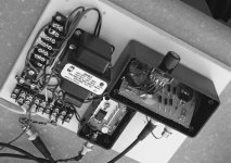
In the mean time, I have built a first prototype, but instead of the BD139/40 pair, I used two pairs of 2N3866/2N5160 that I selected for Vceo>50V, but for the moment, it oscillates madly.
I opted for the RF transistors because the main cause of distortion was the current required to inject/extract charges from the bases of the BD's.
I don't have good models for these transistors though, and this complicates the stability analysis in sim
- Home
- Amplifiers
- Solid State
- Can you improve these amplifiers?