Thanks for the reply John, I like your approach to setting the Iq - did you settle on 1.2ADC or higher? What value R did you finally use to get the desired Iq?
I would be in to get hold of pcb's for this design - are you likely going to do that?
With the kit that Veysol has purchased and using the 5200 with original circuit, I wonder if it will be stable - time will tell.
I would be in to get hold of pcb's for this design - are you likely going to do that?
With the kit that Veysol has purchased and using the 5200 with original circuit, I wonder if it will be stable - time will tell.
Another question John, where you show the value of the electro caps as m - for example, C4 is 2.2m ( I assume that is 220uF) ie, multiply by 100 to give uF.
Multiply by 1,000 instead. It means millifarad - the correct SI unit but typically ambiguous and disliked when you see it printed on a cap. https://www.collinsdictionary.com/dictionary/english/millifarad
Ian is quite right. Trouble was that in the old days before large capacitances were commonplace, many circuits used "m" for microfarads. (and uuF for picofarads). Fortunately that has largely been confined to history.
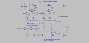
For a PCB design I am thinking about making C4 1mF and C5 10mF with a 10mF PSU capacitor on board. C4 needs to be a tenth of the output cap to drive the bootstrap resistor but maybe 22mF is not really required if people are not likely to need extended bass.
As for the resistor setting the current, this was 639 ohms (470+100+47+22) and the target was 1.2A. But the point is it may need a different setting in a different build depending on the transistor gain.
However, that's another quirk to check. Initial current from cold was actually 1.15A, but after 1 hour the unit had warmed to a stable temperature and the current increased to 1.38A. That was with a 0.7C/W heatsink. It needs a thermal heatsink calculation to prevent thermal run-away (my earlier recommendation was 0.5C/W which seems about right but with transistors like the C5200 there is a significant increase of gain with temperature. )
Last edited:
Thanks for the replies Ian and John, still a bit confused on the electro cap markings. Take C4 for example shown as 2.2m - in the original circuit this cap is 220uF, so I was talking about multiplying the number 2.2 by 100 to give 220uF.
Point noted about the resistor value for Iq and how this would change due to the output transistor Hfe.
I would certainly like to build a pcb for this design, if you are going to do it.
Perhaps it might be clearer for all if you used uF on future schematics, you do have a cap labelled 100uF on the circuit, in the earlier post - just a suggestion.
To stir up this topic again, one copy has already been made according to this scheme, the owner is very satisfied with the sound.
Depletion mosfets were deliberately used because of their advantages over classic bipolar CCS🙂
Depletion mosfets were deliberately used because of their advantages over classic bipolar CCS🙂
Attachments
Last edited:
...should have added that as the assumption is that capacitors are in farads, there should be no need to write the F in, it that was what was confusing you.
With the observation that my C5200 JLH exhibits quite a high change of current with temperature, I considered the heatsink requirements in a little more detail.
The datasheet I have shows a rather alarming change of gain between 100 at 25C and 180 at 100C. This gives a dG/dT of 1.8/75.
If the power at room temperature (say 25C) is Po, the change of power with temperature will be 1.8Po/75. Therefore to ensure that thermal runaway does not occur, the total thermal resistance should be less than 75/(1.8Po).
If you are running your JLH at 27V, 1.2A the power is 32.4W. That makes the total thermal resistance (max) of 1.3K/W. For transistors such as the 2SC5200 the thermal resistance is 0.83K/W. Allowing 0.4K/W for an insulator gives a total of 1.25K/W (approx). Two together make 0.625K/W. So the remaining thermal resistance, which the heatsink must be lower than, is 1.3-0.625=0.675K/W. That means my 0.7K/W is marginal!
If you run your JLH at 32V and 1.2A as my variant would like, that's 40W dissipation and needs 0.4K/W.
OF course that calculation depends on the accuracy of my reading of the gain:temperature graph. I took 180 as being just under the 200 line.
The MJL3281A device shows a gain: temperature change of about 1.5 for 75 degrees rise, so would possibly need a smaller heatsink. The MJ15003, a popular choice, shows a gain change of 80:60 150C:25C giving a figure of merit of 1.33/125, a much nicer value, which may explain why folks have not seen too many thermal issues with those devices.
Seems to me that with the modern transistors, the problem which did not arise with the old 2N3055 (the RCA datasheet shows virtually no gain difference at 1A between 25 and 125C; as well as a gain reduction beyond 1A) may have to be addressed with a temperature controller.
(Yes, I have a design which controls the current, but I'm not prepared to disclose it here).
Last edited:
So, 2SC5200 isn't a good idea for thermal stability, biasing etc. and MJL3281 is better? How does my earlier suggestion of Sanyo (or now KEC + others) 2SD1047 look to you, in a similar comparison?
Last edited:

Thanks again John, I note your thermal calcs and wonder if the better figures for the MJ15003 are due to the TO3 metal package as against the plastic pack for the other 2 transistors.
@Gary - no, the MJ15003 has a lower change of gain with temperature. It's to do with how the chip is constructed, not so much the package, even though the MJ15003 has a thermal resistance of 0.7K/W. For example the 2N3055 I quoted (original RCA hometaxial) has a zero point around 1A where the gain does not change at all, and above that the gain at higher temperatures is less than the 25C one. It has a thermal resistance of 1.5K/W.
Although my calculations are just one-offs, I have not measured the characteristics of 2SC5200 other than through the JLH I have been investigating. As an estimated temperature rise of 53C for my C5200 JLH and a current change from 1.1A to almost 1.4A that is 1.3/53 which is close to 1.8/75 the data sheet implies.
@Ian- From the datasheet I have it looks like a gain change from 100 to 120 for a 100C rise. That makes my figure of merit look like 1.2/100 which certainly seems better!
But (there's always a but, isn't there) it only has a 1.25K/W thermal resistance. That eats into the benefits of a more stable current with temperature.
Last edited:
This may have been covered before in this very long thread, based on your latest design John, what would be your "go to" transistor for the outputs - in either TO3 or the plastic package?
I don't have a "goto" transistor for the JLH, as I have never carried out a detailed investigation. I have posted a comparison in the dim and distant past showing that modern transistors give the best risetimes, which seems to be born out in practice, though I was sceptical of new device in the JLH because they have a large input capacitance. To me that suggests that modern devices need driver transistors to get the best out of them. But, of course, when conducting current all BJT's do have a large input capacitance anyway, and the slower ones quite a bit though some on here would say "charge", but it amounts to the same Q=CV and all that.
If I were to go JLH for stereo, I would be tempted to use the C5200 or MJL3281A but include a thermal corrector. These devices have higher gain compared to the MJ21194 and therefore better suited to an 8 ohm impedance, for lower distortion, and the fastest response which the JLH really needs.
When JLH published his circuit one of the first criticisms was that there was no temperature control, but he was spared having to design around that by virtue of the transistors at the time having better temperature stability, either because of less actual variation or because the gain reduced quite rapidly with higher currents, or both. One obvious solution would be to replace the bootstrap by a transistor-controlled current source as JLH used in his update. The transistor controlling the current could be mounted on the heatsink and would reduce the bias current as the temperature increases, but I've not looked into whether that provides adequate correction, not enough, or too much It may not work for all types because of the range of temp co's as I have discussed, but it may well suit one device type over another. Also, I've tended to keep to the AC coupled unit because if you used the bias transistor to control the current in the DC coupled version, the output rail voltage may drift along with the correction with temperature.
One reason I have kept with the bootstrap is simply to get the highest drive voltage without resorting to an additional power rail. To get the best efficiency the JLH needs the power rails to be kept low - but, as I've mentioned, quasi-saturation will increase distortion near clipping and with modern transistors they may need a few volts more on the supply line anyway for best results. That would mean the overhead of a CCS would not impact the effective output range (of low distortion). Maybe I should look into that.
Last edited:
Far be it from me to question your skills, I don't think I have a quarter of your knowledge, but I think you are on the wrong target.
Have you ever heard of a JLH 69 that had a thermal runaway?
As already said before, I assembled a lot of them, I kept a few, I have one that I never stopped for two years and frankly, I think you have to force the bias or the the power supply voltage like a pig for a JLH to burn out.
For the record, I even have a friend whom I guided by message to assemble his and he forgot to put the insulators under the TO3, and even that didn't destroy anything, he disassembled, put the insulators and thermal paste, switched back on and it sang on the first try.
I remain firmly convinced (after much trial and error) that the most important thing is not to use too fast output peripherals, which must either be paired with a gain greater than 70 and if not possible, to place the one with the highest gain in TR1.
@huggygood,
No, I have not heard of a JLH69 which has had thermal runaway.
I don't know how many have been constructed with modern transistors. But the 2SC5200 which I picked seems to have been the worst choice, which is why I've looked into it. A change of current from 1.1 to 1.4A on a 0.7C/W heatsink is from my perspective unacceptable engineering, even if it does not run away - though I will now leave it switched on for a long time and see what happens. Some users may have been partially protected by using the capacitance multiplier which will see a reduction in supply voltage with increased current which will offset the change by some degree.
Many people will not have used the fast modern transistors because of oscillation, though that as has been discussed in this thread many times, could depend on the construction layout as much as the circuit. And the older transistors, and slower ones, certainly show less variation of gain with temperature, so if that's what most JLH69's have been made with then there would not have been run-away.
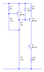
I now offer a simple solution to the 2SC5200 current control whether or not it runs away. This is my first pass at this simple solution but has not yet been tested.
Tr1 is a simple "amplified diode" just like that used in many Class AB amplifiers. It sets a voltage governed by the ratio of R1 to R2. But most of the voltage is dropped across R3 so that the CCS transistor Tr2 operates at a base voltage of about 1.2V. Therefore, if this bias circuit is fed from a constant current (approximately a high value resistor running from the supply rail) the3Vbe's or about -6mV/C is applied to the base of the transistor Tr2. That provides compensation for Tr2 and a further 4mV/C reduction across the emitter resistor.
Values for the resistors may all need optimisation. In this circuit, the simulated standing current actually reduced when included in the JLH-C5200 circuit I posted earlier. This will permit either a smaller heatsink to be used or to control the current, full stop.
Tr1 should of course be mounted on the output transistor heatsink. The circuit may overcompensate if Tr2 does not warm up by adjusting the resistors should permit optimisation. I assume that Tr2 would eventually warm to some degree due to heat from the heatsink raising the temperature of the whole amplifier enclosure. The simulation applies the same temperature change to all transistors currently.
No, I have not heard of a JLH69 which has had thermal runaway.
I don't know how many have been constructed with modern transistors. But the 2SC5200 which I picked seems to have been the worst choice, which is why I've looked into it. A change of current from 1.1 to 1.4A on a 0.7C/W heatsink is from my perspective unacceptable engineering, even if it does not run away - though I will now leave it switched on for a long time and see what happens. Some users may have been partially protected by using the capacitance multiplier which will see a reduction in supply voltage with increased current which will offset the change by some degree.
Many people will not have used the fast modern transistors because of oscillation, though that as has been discussed in this thread many times, could depend on the construction layout as much as the circuit. And the older transistors, and slower ones, certainly show less variation of gain with temperature, so if that's what most JLH69's have been made with then there would not have been run-away.
To recap - I looked into how best to stabilise the JLH69 for high speed transistors, then discovered how large this thermal problem was, or could be. Predictable from the datasheet which I should have looked at first.To restate what I said earlier: The MJ15003, a popular choice, shows a gain change of 80:60 150C:25C giving a figure of merit of 1.33/125, a much nicer value, which may explain why folks have not seen too many thermal issues with those devices.
I now offer a simple solution to the 2SC5200 current control whether or not it runs away. This is my first pass at this simple solution but has not yet been tested.
Tr1 is a simple "amplified diode" just like that used in many Class AB amplifiers. It sets a voltage governed by the ratio of R1 to R2. But most of the voltage is dropped across R3 so that the CCS transistor Tr2 operates at a base voltage of about 1.2V. Therefore, if this bias circuit is fed from a constant current (approximately a high value resistor running from the supply rail) the3Vbe's or about -6mV/C is applied to the base of the transistor Tr2. That provides compensation for Tr2 and a further 4mV/C reduction across the emitter resistor.
Values for the resistors may all need optimisation. In this circuit, the simulated standing current actually reduced when included in the JLH-C5200 circuit I posted earlier. This will permit either a smaller heatsink to be used or to control the current, full stop.
Tr1 should of course be mounted on the output transistor heatsink. The circuit may overcompensate if Tr2 does not warm up by adjusting the resistors should permit optimisation. I assume that Tr2 would eventually warm to some degree due to heat from the heatsink raising the temperature of the whole amplifier enclosure. The simulation applies the same temperature change to all transistors currently.
Attachments
Last edited:
... and for those of you contemplating using TTC5200's (genuine, I hope) there is better news. The datasheet shows typical gains of (an approximate) 120 to 180 over a 75C change, which is at least an improvement over the 2SC5200. According to datasheets I have.
I respect your work and your complete answer.
nevertheless and without hindering your development work, for me a jlh must remain original, that's what gives it its charm and the only modifications I have validated are the bias and midpoint pot and the increase in the bootstrap capacitor but as soon as you touch something else, it's no longer a 69, it's something else.
nevertheless and without hindering your development work, for me a jlh must remain original, that's what gives it its charm and the only modifications I have validated are the bias and midpoint pot and the increase in the bootstrap capacitor but as soon as you touch something else, it's no longer a 69, it's something else.
- Home
- Amplifiers
- Solid State
- JLH 10 Watt class A amplifier