I want to but very busy at work. No time for DIY for next 1-2 years.and you don't want to assemble it?
I also have a pair of pcb, it stays on my todolist.
Hi John, with reference to the latest schematic attached to the above post with the diode across B-E of TR3, I also notice the value has changed of the feedback resistor R13 - shown as 1.2K instead of the usual 2.7K, any reason for this?
The story so far ...
Implementing the thermal compensation circuit, the quiescent current stabilised.
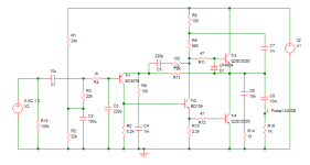
Value of resistor R10 in the attached circuit depends on the heatsink used: 1.6k suited my 0.7K/W but if you use a 1K/W then the temperature will increase further, so may need to be increased to 1.8k. Maybe calculate some values for different heatsinks but greater than 1K/W is not recommended.
Diode suggested in update 1 works well but the driver current is pulsed to several 100mA on a fast square wave input. That drives the lower output transistor to several amps. Adding a second diode will prevent the output capacitor discharging through the lower output transistor in the event of a short circuit. There is still a very short pulse due to the capacitance of the extra diode but it is at a lower value than not using it, and only for a very short duration.
Transistor Tr1 (thermal compensation ) should be mounted on the output transistor heatsink. Tr2 should be mounted on the same angle bracket (if used). In my setup it is mounted on a 21K/W twisted finger type heatsink. It heats up more quickly than the output transistors. As the compensation circuit is passive the Vbe of Tr2 affects the current. So, the current increases at first but as the main heatsink temperature catches up the current is brought back down.
Now I was prepared to test the circuit with a 1uF capacitor load. It is stable, but exhibits some damped ringing. Since the circuit really isn't capable of driving lower load impedances than the design target a capacitive load is not recommended. Damping can be controlled if necessary with a 0.47 ohm resistor in series with the output.
That's about it I think. Maybe check the distortion again and perhaps even listen to it.
Implementing the thermal compensation circuit, the quiescent current stabilised.
Value of resistor R10 in the attached circuit depends on the heatsink used: 1.6k suited my 0.7K/W but if you use a 1K/W then the temperature will increase further, so may need to be increased to 1.8k. Maybe calculate some values for different heatsinks but greater than 1K/W is not recommended.
Diode suggested in update 1 works well but the driver current is pulsed to several 100mA on a fast square wave input. That drives the lower output transistor to several amps. Adding a second diode will prevent the output capacitor discharging through the lower output transistor in the event of a short circuit. There is still a very short pulse due to the capacitance of the extra diode but it is at a lower value than not using it, and only for a very short duration.
Transistor Tr1 (thermal compensation ) should be mounted on the output transistor heatsink. Tr2 should be mounted on the same angle bracket (if used). In my setup it is mounted on a 21K/W twisted finger type heatsink. It heats up more quickly than the output transistors. As the compensation circuit is passive the Vbe of Tr2 affects the current. So, the current increases at first but as the main heatsink temperature catches up the current is brought back down.
Now I was prepared to test the circuit with a 1uF capacitor load. It is stable, but exhibits some damped ringing. Since the circuit really isn't capable of driving lower load impedances than the design target a capacitive load is not recommended. Damping can be controlled if necessary with a 0.47 ohm resistor in series with the output.
That's about it I think. Maybe check the distortion again and perhaps even listen to it.
Attachments
Last edited:
TTL-logicAdding a second diode
Attachments
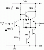
The function of diode D1 is to prevent even the slight conduction of Q3, when the output is low. Voltage drop across the diode D1 keeps the emitter diode of Q3 reverse biased and so only Q4 conducts during the low output condition.TTL-logic
It has been remarked often that JLH's amplifier looks like a TTL gate.
I agree, adding the power diode makes it look even more so.
I agree, adding the power diode makes it look even more so.
Thanks for the further update John. I will be using a way oversized heatsink (suits the chassis design) with a specified thermal resistance of 0.28 deg C / watt - so for the 42watts total channel dissipation, that only gives a worst case 12 deg C heatsink temp rise above ambient. I assume I would not need the thermal comp circuit you show in the latest design in post # 9406?
Also, do you think your latest design presuming you are happy with it and it sounds just right, might morph into a pcb design for us to get our hands on?
Also, do you think your latest design presuming you are happy with it and it sounds just right, might morph into a pcb design for us to get our hands on?
I would not build a JLH without temperature compensation. Especially now a simple one can be made to work.
The main reason is to accommodate varying room temperatures as much as self-heating. WHole point of my investigation was to see what happened with modern transistors. No significant gain fall-off with current until much higher currents than older devices, so they are prone to quiescent current drift even if runaway is avoided.
With the two protection diodes it is more important to use a CCS driver stage because that's added another non-linearity to the upper transistor. A CCS will minimise the differences between the two outpuit halves.
I'd still expect higher frequency audio to have slightly higher distortion due to the compensation capacitor which lowers the driver stage resistance at higher frequencies, but I think this is a workable design.
OK, thanks John, so no problems to include the temp comp cct.
Interested in your thoughts once you have a listen to the build.
Interested in your thoughts once you have a listen to the build.
Well, these are certainly unusual types of mod. to include in a JLH type amplifier. I wasn't expecting thermal drift or runaway to be problem because I've seen so many JLH builds that use either 2SC5200 or some other modern, low cost power transistor rather than an antique style TO3 from the distant past. I haven't even heard of a thermal drift issue with modern transistors and this is coming from a country where summer heat really is a problem for using class A amplifiers. Maybe I should check with a few audio DIY groups and find out what their recent JLH problems have been.
There are more than one type or grouping of modern power semis; some having low Ft, others high. e.g. MJL21193/4 as opposed to MJL1302/3281 or 2SC5200/2SA1943, to name the popular ones. My question is therefore, would you expect the low Ft types to show similar thermal drift problems to the higher Ft types?
There are more than one type or grouping of modern power semis; some having low Ft, others high. e.g. MJL21193/4 as opposed to MJL1302/3281 or 2SC5200/2SA1943, to name the popular ones. My question is therefore, would you expect the low Ft types to show similar thermal drift problems to the higher Ft types?
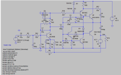
Pay attention to Q3. This is a bootstrap current source (LKA\Danhart). https://photos.app.goo.gl/gj1ySGc3jfbzSu7q8With the two protection diodes it is more important to use a CCS driver stage
Attachments
Last edited:
Well Ian, looking at some of those heatsinks on the multitude of JLH1969 kits that seem to be on Aliexpress, it would not surprise me at all that some of those builds could fall foul of thermal runaway. Many are quite small, even allowing for some of the kits specified as running of lower rail voltage.
As soon as it is connected to the JLH, there will be a load and the VDC will sag. Do not worry about this.Hello fellow DIYers. Recently my wife said I needed a hobby, and know I used to be into car audio thought I'd like to get back into it, but for the home. So she got me the JLH1969 with the 3055s from Ebay. Pretty cool. I bought a toroidal from Antek (20v x2 @5A per coil) and the recommended psu module for the amp from Ebay also. My question is after that 20vac gets changed to dc (20vac x 1.414= 28.3 or higher with no load) is this too high a voltage? Should I get an 18vac x 2? I don't want to ruin anything. Sorry for an absolute noob question but we all have to start somewhere.
Yes, the heatsinks included in the cheapest kits seem to be only token sized - perhaps enough for use with a nominal 12V DC power source which would likely be available and safer for handling by newbies and older kids everywhere..... looking at some of those heatsinks on the multitude of JLH1969 kits that seem to be on Aliexpress, it would not surprise me at all that some of those builds could fall foul of thermal runaway......
There's also a likely question as to why your power transistors may only be TIP41! As newbies make up the largest part of the cheap kits market, I do think it makes sense to begin with low power. They can then leave the better informed DIYs to choose component sizes by referring to online articles and discussions like this thread or make their assessments from the original 10W design details and later developments.
Last edited:
John Linsley Hood proposed a current control circuit in at least one of, if not the original, article. So it is not a new phenomenon - as I posted, many criticised the design at the time for not having any thermal control. He only mentioned the need for compensation if high temperatures were expected or small heatsinks were to be used.
It was the surprising change of current I found using 2SC5200 during warm-up that caused me to revisit this, particularly as I was not using a small heatsink.
JLH's current control simply used a transistor to shunt current from the driver as the amplifier warms up. It's a good idea, but his implementation only offset what a Vbe offset gives, which I have not delved into.
The solution I came up with allows independent control of the thermal adjustment so that it can be set to give a stable current, as the Vbe multiplier ratio is used to set the control needed. The resistors may need fine tuning to achieve that.
While considering the stability issue in a capacitive load that reminded me of another factor JLH does not appear to have considered - that of reverse biasing the upper output transistor on a fast switching waveform. You could insert a diode in series with the base, or shunt the base as I have suggested but add another diode to prevent reverse bias in the event of a shorted load while a signal is applied. (This would not be a problem in a complementary output stage when the PNP would be turning on and the reverse voltage on the NPN would be limited).
So that leads to needing a constant current source rather than keeping a bootstrapped resistor which may well increase distortion because of the increased asymmetry. Combining this with the thermal compensation circuitry shows, in simulation, barely any effect on distortion.
You could bootstrap the current source at greater complexity as OldDIY showed. I suspect that would need some additional filtering and I would recommend, instead, if the overhead of the CCS was too much of a limitation on output power, to run the CCS from a slightly higher rail voltage, which can be fed from a voltage doubler on the PSU rectifiers quite easily.
Whether low fT transistors would see the same drift: the data sheet for the MJL21194 shows a gain change of about 65 to about 110 between 25C and 100C, so yes. It is not the fT so much as the point at where the gain rolls off. The new devices typically reach 4 or 5A before a significant fall in gain is reached. Those old transistors like TIP3055 had a peak gain below 1A and so the gain roll off with increasing current helps to stabilise the circuit. And the original 2N3055 also actually had a zero drift point at about 1A. Whether recently manufactured TIP3055's or the like have the same characteristics as the older ones is something else I've not looked into. They might well be different.
I too would be interested to hear of people's experiences with 2SC5200 and other new devices in the JLH, and how folks get on with the kits which are offered. If any have problems with the current increasing with temperature the solution I proposed might help.
Whether the protection diodes are needed depends on whether you plan to use the circuit for anything other than audio - or want a safer circuit!
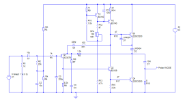
Postscript - the update 2 circuit shows a 1k resistor across the input. That was for simulation purposes only. It should have been 100k as a tie down for the input capacitor.
There is also a 47nF and 10 ohm resistor missing across the output rail. The so-called Zobel network is important to keep the OLG well defined at high frequencies. (Unfortunately it loads the circuit so limits the output power at around 300kHz). There should be a 1k resistor as a tie down for the output capacitor too.
There is also a 47nF and 10 ohm resistor missing across the output rail. The so-called Zobel network is important to keep the OLG well defined at high frequencies. (Unfortunately it loads the circuit so limits the output power at around 300kHz). There should be a 1k resistor as a tie down for the output capacitor too.
- Home
- Amplifiers
- Solid State
- JLH 10 Watt class A amplifier