If you want 120Hz HP your C1=47nF is too small, but if you want to implement the crossover in the Quad we need more information.The Quad can give you 3rd order but not 4th
Thanks! I am having difficulty answering your question. Why do you say C1 is too small, i have listened to the quad and C1 is cutting the bass off very nicely which is what i want.
And why do you say : " if you want to implement the crossover in the quad " I have already explained the 47nf cap is in the quad
The attenuation rate of the subwoofer is 12db/octave
Thanks
I know where the capacitor is. What I don't know is why you are implementing the crossover in the Quad rather than externally, and you haven't answered that.
If you want to match 12dB/octave it is not just a matter of changing one capacitor. You have to change two, by definition. For 120Hz you need something like C1=60nF, C4=13nF (assuming R6=100k). But actually it's more complex than that.
Of course if you're only aiming to 'cut the bass off nicely', rather than actual precision and a properly complementary crossover characteristic, I really don't know why you're even asking.
Thanks! What component values would you use to reduce the quad sensitivity, and at the same time roll of the low frequencies, everything under 150hz or so
I'm not so sure I would use that approach but you could try C1=27nF, R3=30k, R6=100k, R4=7k5, C4=12nF and C2=5.6uF
Why not just set the gain conventionally to whatever you want, forget Quads weird designed for ESL speaker response and then add a proper opamp based filter at the input as @ejp seems to be suggesting.
Thanks! I put the 47nf cap into the quad years ago to attenuate the response, and also it allowed me to connect the quad straight to the speakers, without needing to put the time and effort in to design a crossover for the speakers. And without a crossover i'm not getting the usual crossover problems such as ringing, phase reversal, crossover distortion, so sound quality is improved as well.
When you say " add a proper opamp filter " I guess you mean the quad version is not so good. What would you suggest as an alternative
When you say " add a proper opamp filter " I guess you mean the quad version is not so good. What would you suggest as an alternative
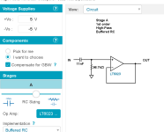
Have a play with this. Its easy to use and is web based (nothing to install). You put in what you want and the wizard will do the rest.What would you suggest as an alternative
https://tools.analog.com/en/filterwizard/
Sound quality is improved': this is simply untrue. You have a 2nd-order LP and a first-order HP. These do not sum correctly in the crossover region, and in that region you also have 180 degrees LP shift and 90 degrees HP shift, which causes major phase errors. You also have a lumpy bass response in the HP, displayed above, because you've only changed one filter out of the three that are in effect. So your frequency response isn't flat and your phase response is all over the shop. 'without a crossover i'm not getting the usual crossover problems such as ringing, phase reversal, crossover distortion, so sound quality is improved as well.
I suggest you restore the Quad to its factory state and get something like a MiniDSP,, program it for a 2nd-order Butterworth LP response to the subwoofer, to sum with its own 2nd-order response to make 4th order, and program the HP to be 4th order Linkwitz-Riley. Assuming the wubwoofer is Butterwrth this will give you 4th-order Linkwitz-Riely in both LP and HP, which is the only filter configuration that sums to flat throughout the crossover region. A bit more work but the results are certainly worth it. I've done this and I also added some baffle correction to the LP so I have measured room frequency response flat from 20-20kHz.When you say " add a proper opamp filter " I guess you mean the quad version is not so good. What would you suggest as an alternative
Have a play with this. Its easy to use and is web based (nothing to install). You put in what you want and the wizard will do the rest.
https://tools.analog.com/en/filterwizard/
View attachment 1174085
This is what the tool comes up with, certainly a lot simpler than the quad version, to give the desired attenuation at 150hz
What do you think
Thanks!
Attachments
Its perfect if that is what you want.
Now you can easily do that response with the Quad alone. This has the gain lowered and the output of the amp attenuated to equal the filter level for easy comparison. The two traces overlay each other.
The only thing to watch is that you feed the Quad from a low source impedance.


Now you can easily do that response with the Quad alone. This has the gain lowered and the output of the amp attenuated to equal the filter level for easy comparison. The two traces overlay each other.
The only thing to watch is that you feed the Quad from a low source impedance.
Thanks! In the quad i am currently using the opa627 opamp, is that okay
Are the components in the red circle are for removal?
For the source i am using the hidizs dac, does this have the required low impedance that you mentioned
Hidizs S8 technical specifications:
Also, will this new circuit give better sound quality than the quad based one in post # 383 as you said the quad design is " weird "
Why have you placed a big red arrow at the speaker output
Thank you
Are the components in the red circle are for removal?
For the source i am using the hidizs dac, does this have the required low impedance that you mentioned
Hidizs S8 technical specifications:
- DAC: CS43131
- DSD: 64/128/256 HW
- PCM: 32bit/384kHz
- Output: 30mW + 30mW @ 32Ω
- FR respone: 20-50kHz
- THD+N: 0.002% @ 1kHz
- SNR: 120dB
- Channel Separation: 120dB @ 32Ω
- Output impedance: <1Ω
- Recommended resistance: 8-150Ω
- Buttons: Volume +/-
- Audio jack: SE 3.5mm /mic supported
Also, will this new circuit give better sound quality than the quad based one in post # 383 as you said the quad design is " weird "
Why have you placed a big red arrow at the speaker output
Thank you
Last edited:
I think it's a first order filter that doesn't match the second-order LP filter to the subwoofer, and that is not itself adequate anyway. I've said all this before.What do you think
And 30mW into 32 ohms is about 950mV into 22k, so your gain change has gone too far.
But if you think it's good why are you even asking?
Last edited:
I would think so. I assume its working OK now in the standard setup.Thanks! In the quad i am currently using the opa627 opamp, is that okay
It says <1 ohm so that is very low. The thing to avoid was feeding the Quad directly from say the wiper of a 20k pot.For the source i am using the hidizs dac, does this have the required low impedance that you mentioned
I think you are misunderstanding the diagram 🙂 The 11nF and 96.7k are not needed. They are in the simulation to show the response those parts give (the same as the filter wizard). That is the response you say you wanted. The opamp from the wizard isn't needed for the sim because we are not driving any load. The opamp was just a buffer.The positive and negative circle on the left is the input, can i solder the 11nf input cap immedialtly after this, then solder R8 96.7k across R1 220k
Those are the values needed for the Quad to give that same response as the 11nF 96.7k filter (you can use a 220uF cap for C2 though).Are the components in the red circle are for removal?
Just to show the attenuated feed to match the output level to that of the filter. Remember we are looking at the 11nF 96.7k filter and making the Quad to match that.Why have you placed a big red arrow at the speaker output
Only you can answer that one by listening.Also, will this new circuit give better sound quality than the quad based one in post # 383 as you said the quad design is " weird "
Thanks! I can place a resistor after the dac if you think it may help.
It confused me a little, when you said to forget the quad design and use a proper input, i thought the design was going to totally utterly change, i imagined i was going to be using the resistor and cap that the wizard had recommended, that's why i thought all those components were going to be removed
It confused me a little, when you said to forget the quad design and use a proper input, i thought the design was going to totally utterly change, i imagined i was going to be using the resistor and cap that the wizard had recommended, that's why i thought all those components were going to be removed
A resistor after the DAC won't do anything apart from raise the output impedance. I would just use it as designed.
T=C*R so 11nF * 96.7k = 0.0010637 seconds.
C1 = 47nF.
R3 should be 0.0010637/47E-9 which is actually 22631 ohms (22k is near enough). That exact resistance value exactly matches the filter response over the range you want.
This is with R3 at 22631 ohm. What you are seeing are the two circuits running together, the filter wizard circuit and the Quad. The traces overlay each other only diverging below 10Hz.

Even that divergence can be altered.
C2 is now 1000uF (I don't recommend this because the amp may take a lot longer to 'settle' at power on and cause switch on thump) and C4 10uF.

Nope, we just make the cap in the feedback arm a 1uF to extend the LF response. Value of C1 and R3 need to give the same time constant as the 11nF and 96.7k of the filter.i thought the design was going to totally utterly change
T=C*R so 11nF * 96.7k = 0.0010637 seconds.
C1 = 47nF.
R3 should be 0.0010637/47E-9 which is actually 22631 ohms (22k is near enough). That exact resistance value exactly matches the filter response over the range you want.
This is with R3 at 22631 ohm. What you are seeing are the two circuits running together, the filter wizard circuit and the Quad. The traces overlay each other only diverging below 10Hz.
Even that divergence can be altered.
C2 is now 1000uF (I don't recommend this because the amp may take a lot longer to 'settle' at power on and cause switch on thump) and C4 10uF.
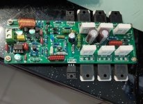
I can use QUAD707 for sale.Sorry, not referring to any schematic, just read something in this thread about harsh brittle treble, and op amp circuitry being the culprit, think on page 3 # 45
It is better than QUAD405. Using 12 2SD718 TO 3P3 transistors
QUAD405 does not require any modifications.
No matter which output transistor you use. It doesn't make any difference.
The premise is that it will not be damaged. If damaged, there will be a DC output.
If there is no damage. No transistor has any effect difference.
The performance of QUAD405 is not very good.
Attachments

As a merchant. I enjoy selling class D amplifiers.How do you think the quad may compare against the hypex nc122mp. Hypex seem to be popular amps at the moment, and i'm thinking of building one. Do you think there may be any audible improvements compared aganist the quad
But if I use it myself. I will assemble a class AB amplifier.
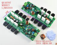
Recommend you QUAD-707
Attachments
I use a Hypex NC122MP based amp during the summer months. Compared with my DIY valve amps, an ACA and a Quad 303 power amp (both driven by a Whammy) the Hypex is very 'clean' and powerful sounding but not as much fun to listen to.
There are many clean and powerful amplifiers. There are too many of them.I use a Hypex NC122MP based amp during the summer months. Compared with my DIY valve amps, an ACA and a Quad 303 power amp (both driven by a Whammy) the Hypex is very 'clean' and powerful sounding but not as much fun to listen to.
But I think no matter how many amplifiers there are. The most commonly used is still Class AB.
For example, QUAD707 is a class B amplifier. Not much heat.
It's very clean. We don't need too many amplifiers.
Although I have designed and produced many amplifiers. But I don't love DIY.But that's your business. As I'm a person whose hobby is building amps and listening to music, then you can never have too many (space permitting).
Because I think it takes too much time and is tiring.
If I want to make an amplifier. It must meet my very high requirements.
In fact, I wouldn't be interested in 99% class D amplifiers. I don't need too many amplifiers.
Unless it is excellent in all aspects.
- Home
- Amplifiers
- Solid State
- QUAD 405 clone